Quantcast
Channel: Electronics FAQ
Viewing all 56 articles
Browse latest View live

Inside a WorldSpace satellite radio receiver

$
0
0
WorldSpace is no longer operational. But I had a receiver lying around from when it was active. I opened it up and here is what I found in it:

Antenna Unit

Front Panel

Inside of the front panel

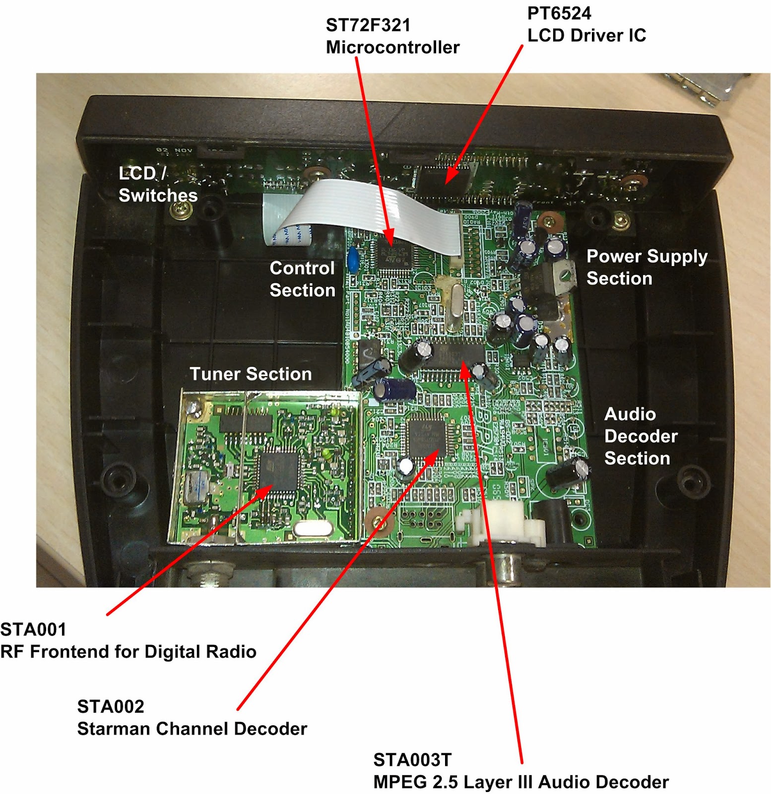
Main Board

Mainboard with the various sections marked out

STA001 – RF Frontend for Digital Radio
  • Single chip receiver for satellite digital transmission
  • Superheterodyne receiver with IF output
  • High input intercept point, low Mixer noise
  • 54db IF VGA gain range
  • Adjustable RF gain
  • Adjustable IF gain 
  • Integrated RF VCO
  • Integrated IF VCO
  • Integrated synthesizer
  • I2C bus compatible programming Interface
  • Unregulated 2.7 volts to 3.3 volts voltage Supply
  • Low cost external components
Block Diagram of STA001 – RF Frontend for Digital Radio

STA002 – Starman Channel Decoder
  • Front end interface
    • IF input carrier frequency: f = 1.84 MHz
    • Single internal 6 bit A/D converter
    • QPSK demodulation
    • Input symbol frequency: Fs = 1.84 Msymbols/s
    • Digital Nyquist root filter:
      • Roll-off value of 0.4
    • Digital carrier loop:
      • On-chip quadrature demodulator and tracking loop
    • lock detector
    • C/N indicator
    • Digital timing recovery:
      • Internal timing error evaluation, filter and correction
    • Digital AGC:
      • Internal signal power estimation and filter
      • Output control signal for AGC (1 bit PWM)
  • Forward error correction
    • Inner decoder
      • Viterbi soft decoder for convolutional codes, constraint length M=7, Rate 1/2
    • Deinterleaver block
    • Outer decoder
      • Reed-Solomon decoder for 32 parity bytes; correction of up to 16 byte errors
      • Block lengths: 255
      • Energy dispersal descrambler
  • Back end Interface
    • Broadcast Channel selection
    • Audio Service Component selection to MPEG decoder
    • Service Component selection
  • Control
    • I2C serial Bus control interface
  • Decryption
    • WES Scheme
Block Diagram of STA002 – Starman Channel Decoder


STA003T – MPEG 2.5 Layer III Audio Decoder
  • Single chip MPEG2 layer 3 decoder
  • Supporting
    •  All features specified for Layer III in ISO/IEC 11172-3 (MPEG 1 Audio) except 44.1KHz Audio
    • All features specified for Layer III 2 channels in ISO/IEC13818-3.2 (MPEG 2 Audio) except 22.05KHz Audio
    • Lower sampling frequencies syntax extension, (not specified by ISO) called MPEG 2.5 except 11.025KHz Audio
  • Decodes layer III stereo channels, dual channel, single channel (mono)
  • Supporting the MPEG 1 & 2 sampling frequencies and the extension to MPEG 2.5:
    48, 32, 24, 16, 12, 8 kHz
  • Accepts MPEG 2.5 layer III elementary compressed bitstream with data rate from 8 kbit/s up to 128 kbit/s
  • Digital volume control
  • Digital bass & treble control
  • Serial bitstream input interface
  • Ancillary data extraction via I2C interface.
  • Serial PCM output interface (I2S and other formats)
  • PLL for internal clock and for output PCM clock generation
  • Low power data elaboration for power consumption optimisation
  • CRC check and synchronisation error detection with software indicators
  • I2C control bus
  • Low power 3.3 volts CMOS technology
  • 14.72 MHz external input clock or built-in crystal oscillator
    Block Diagram of STA003T – MPEG 2.5 Layer III Audio Decoder

PT6524 – LCD Driver IC
  • CMOS Technology 
  • Up to 4 Common and 51 Segment Drivers 
  • Up to 204 LCD Segments 
  • Up to 12 General Purpose Output Ports 
  • 1/4 Duty – 1/2 Bias or 1/4 Duty – 1/3 Bias Drive Technique 
  • No Decoder Intervention Necessary to Display the Data 
  • Power Saving Mode provided 
  • RC Oscillation Circuit
Block Diagram of PT6524 – LCD Driver IC


ST72F321 – Microcontroller
  • Memories
    • 32K to 60K dual voltage High Density Flash (HDFlash) or ROM with read-out protection capability. In-Application Programming and In-Circuit Programming for HDFlash devices
    • 1K to 2K RAM
    • HDFlash endurance: 100 cycles, data retention: 20 years at 55°C
  • Clock, Reset And Supply Management
    • Enhanced low voltage supervisor (LVD) for main supply and auxiliary voltage detector (AVD) with interrupt capability
    • Clock sources: crystal/ceramic resonator oscillators, internal RC oscillator, clock security system and bypass for external clock
    • PLL for 2x frequency multiplication
    • Four Power Saving Modes: Halt, Active-Halt, Wait and Slow
  • Interrupt Management
    • Nested interrupt controller
    • 14 interrupt vectors plus TRAP and RESET
    • Top Level Interrupt (TLI) pin on 64-pin devices
    • 15 external interrupt lines (on 4 vectors)
  • Up to 48 I/O Ports
    • 48/32 multifunctional bidirectional I/O lines
    • 34/22 alternate function lines
    • 16/12 high sink outputs
  • 5 Timers
    • Main Clock Controller with: Real time base,
    • Beep and Clock-out capabilities
    • Configurable watchdog timer
    • Two 16-bit timers with: 2 input captures, 2 output compares, external clock input on one timer,  PWM and pulse generator modes
    • 8-bit PWM Auto-reload timer with: 2 input captures, 4 PWM outputs, output compare and time base interrupt, external clock with event detector
  • 3 Communications Interfaces
    • SPI synchronous serial interface
    • SCI asynchronous serial interface 
    • I2C multimaster interface
  • 1 Analog peripherals
    • 10-bit ADC with up to 16 input ports
  • Instruction Set
    • 8-bit Data Manipulation
    • 63 Basic Instructions
    • 17 main Addressing Modes
    • 8 x 8 Unsigned Multiply Instruction
  • Development Tools
    • Full hardware/software development package
    • In-Circuit Testing capability
Block Diagram of ST72F321 - Microcontroller


Plug in Lamp Dimmer - The Jugaad Way

$
0
0

My cousin sister left me an awesome Floor Lamp (Ikea Orgel Vreten Floor Lamp). Since, the lamp was bought from USA, I had to modify it by installing alternate holders for the bulbs available here in India. Indian bulbs had different threading.

The Floor Lamp
Once that was done, I started thinking of ways to neatly install a dimmer for it since I couldn't find Indian equivalent for the American/European ones like this one here.

I tried to stick one to the plug - it worked - but looked really ugly:

First try
Then one day, I remembered to  ask Rohit Garg, if he had a better way of getting this done, and he did. He used an adapter casing and installed a dimmer inside it. He also added a metal knob to make it look even better:
Plug in Dimmer made by Rohit
I got another brainwave to use the white three core ironing cable to replace the lamp's existing black one to match the white walls.

Ironing Cable
Floor Lamp with the jugaad dimmer installed
As an after thought, I added a pair of 2 pin socket/plug pair to easily attach detach the dimmer to the lamp.

Adding 2 pin socket plug pair to the dimmer casing
The whole effort cost me less than 400 rupees - a lot less than the 10.80 GBP Plug in Dimmer I was vying for. In case you have a similar lamp (not that this works only for bulbs and not CFLs or LED lamps) requiring addition of a dimmer, do feel free to contact Rohit over phone or by visiting his shopfront on Aundh Road, Pune at the address below:


A lamp that shimmers when your sweetheart mentions you in her tweet (Arduino Yun + Temboo)

$
0
0
I have talked out my Floor Lamp (Ikea Orgel Vreten Floor Lamp) and how I got a Jugaad Plug-in Dimmer made for it. I had an Arduino Yún lying around and had just read up on Temboo. That's when I realized I could use the Arduino to control the lamp from the internet very easily. I noticed that Temboo could fetch tweets and so I got an idea - I could program the Arduino to dim in and dim out the lamp whenever @ZeniaIrani mentioned me in her tweets. I call the project "The Zenomaniac's Lamp"

Here is how I got it done:
  1. Configured the Arduino Yún to connect to to my WiFi. Installed the latest version of Arduino IDE on my PC.
  2. Bought a 5V cell phone charger
  3. Brought the digital from Sunrom: http://www.sunrom.com/249
  4. Assembled the circuit and installed everything in a plastic lunch box. I used white three cored cable used for electric irons for the AC input and AC output - they are long lasting and look nice. Installed 2 pin socket and plugs on the ends of the wire for easily attaching/detaching of the circuit to the lamp.
  5. Read up on the instructions and code for fetching tweets here: https://www.temboo.com/arduino/read-a-tweet
  6. Got a Temboo account. The free account allows you to add only one application. I renamed my default application (My Account > Applications) to "Zenomania" and noted down the application key. The free plan will allow you only 1000 calls per month - meaning you can check your twitter feed only that many times in a given month window before the thing stops working - this is sad!
  7. Got a Twitter Dev account - visit this link, login with your usual twitter account and create an application. I named mine "Zenomania". The Temboo application running on Arduino Yún requires four things - Access token, Access token secret, API key, API Secret. The API Key and API secret are shown on the API keys tab under the Application Management page. For the Access token and Access token secret, I had to click on "Test OAuth" Button - twitter then asked me to sign in once again with my twitter credentials and then displayed the Access token and secret.
  8. I added the secrets and API keys to the Temboo read-a-tweet example and downloaded the code to Arduino over the network. The Temboo keys go into TembooAccount.h where as the Twitter keys go into the .ino file. Once I was able to get the example to working, I moved on to the next step.
  9. I modified the Temboo read-a-tweet code so that instead of fetching tweets from my timeline, it instead fetched tweets that mentioned me. I added a function to shimmer the lamp - cycle through the 16 levels (to and fro) of dimming supported by the sunrom's digital dimmer. From the code I would call the Temboo API to fetch the latest tweet that mentions me every 65 seconds (Twitter has throttling active on all apps - you can fetch data only 15 times in a 15 minutes window before you are blocked until the end of that window). I would then check if the tweet is new and if its by ZeniaIrani. If yes, I enable the lamp to shimmer for the next 65 seconds until I check for tweets again.
  10. So once ZeniaIrani mentions me in a tweets, it may take upto 65 seconds before the lamp starts blinking. As mentioned earlier, because of limitations imposed by twitter, we can't check the tweets more often otherwise we will start getting HTTP error codes. Similarly, once you run out of 1000 API calls per month, the lamp will stop working till the end of the 30 days period. Temboo might not be that great after all.
The Connection Diagram

16 Step dimmer modules from Sunrom.
There are also 256 Step ones available that can be
controlled using a single UART pin.

A lunch box to put everything in.
D'Cold for curing the stuffy nose syndrome.

The Arduino, dimmer and power supply for Arduino all connected.
White colored power supply was actually a phone charger.

Everything mounted neatly inside the lunchbox.
I had to break open the phone charger shell to decrease its size,
so that I could fit everything inside the box.
Used hot glue gun to stick everything inside.
For Arduino, I used screws and mounted it on the inside of the lid.

The Zenomaniac's lamp - All installed, online and working

The Shimmering Zenomaniac's Lamp

Zenomania.ino
(Assign your Twitter keys and key secrets to the four string constants declared in the beginning of the code. Modify the author name in line 123 to your own sweetheart's name)

  1
2
3
4
5
6
7
8
9
10
11
12
13
14
15
16
17
18
19
20
21
22
23
24
25
26
27
28
29
30
31
32
33
34
35
36
37
38
39
40
41
42
43
44
45
46
47
48
49
50
51
52
53
54
55
56
57
58
59
60
61
62
63
64
65
66
67
68
69
70
71
72
73
74
75
76
77
78
79
80
81
82
83
84
85
86
87
88
89
90
91
92
93
94
95
96
97
98
99
100
101
102
103
104
105
106
107
108
109
110
111
112
113
114
115
116
117
118
119
120
121
122
123
124
125
126
127
128
129
130
131
132
133
134
135
136
137
138
139
140
141
142
143
144
145
146
147
148
149
150
151
152
153
154
155
156
157
158
159
160
161
162
163
164
165
166
167
168
169
170
171
172
173
174
175
176
177
178
179
180
181
182
183
184
185
186
187
188
189
190
191
192
193
194
195
196
197
198
/*
ReadATweet

Demonstrates retrieving the most recent Tweet from a user's home timeline
using the Temboo Arduino Yun SDK.

This example code is in the public domain.
*/

#include <Bridge.h>
#include <Temboo.h>
#include "TembooAccount.h" // contains Temboo account information

/*** SUBSTITUTE YOUR VALUES BELOW: ***/

// Note that for additional security and reusability, you could
// use #define statements to specify these values in a .h file.
constStringTWITTER_ACCESS_TOKEN="5ghgfhgfhgfhgfhgfhgfhgfhgfhgfhgfhghfgJ";
constStringTWITTER_ACCESS_TOKEN_SECRET="9xSrXMhIhgjdfkjghdfgjdfkljgXrgumB24";
constStringTWITTER_CONSUMER_KEY="ECfgkjhdfkjgjdfhgkjdhfkrQ";
constStringTWITTER_CONSUMER_SECRET="Tt9lgfjdfklgjdfkljgfkGjU";

Stringlast_author;
Stringlast_tweet;

unsignedchardim_val=0;
unsignedchardim_dir=0;
unsignedchardim_state=1;
unsignedintloop_ctr=0;

voidsetup(){
pinMode(2,OUTPUT);
pinMode(3,OUTPUT);
pinMode(4,OUTPUT);
pinMode(5,OUTPUT);

Bridge.begin();
}
voidloop()
{

TembooChoreoHomeTimelineChoreo;
if(loop_ctr==650){// wait 65 seconds between HomeTimeline calls
loop_ctr=0;
// invoke the Temboo client.
// NOTE that the client must be reinvoked, and repopulated with
// appropriate arguments, each time its run() method is called.
HomeTimelineChoreo.begin();

// set Temboo account credentials
HomeTimelineChoreo.setAccountName(TEMBOO_ACCOUNT);
HomeTimelineChoreo.setAppKeyName(TEMBOO_APP_KEY_NAME);
HomeTimelineChoreo.setAppKey(TEMBOO_APP_KEY);

// tell the Temboo client which Choreo to run (Twitter > Timelines > HomeTimeline)
HomeTimelineChoreo.setChoreo("/Library/Twitter/Timelines/Mentions");

// set the required choreo inputs
// see https://www.temboo.com/library/Library/Twitter/Timelines/HomeTimeline/
// for complete details about the inputs for this Choreo

HomeTimelineChoreo.addInput("Count","1");// the max number of Tweets to return from each request
HomeTimelineChoreo.addInput("AccessToken",TWITTER_ACCESS_TOKEN);
HomeTimelineChoreo.addInput("AccessTokenSecret",TWITTER_ACCESS_TOKEN_SECRET);
HomeTimelineChoreo.addInput("ConsumerKey",TWITTER_CONSUMER_KEY);
HomeTimelineChoreo.addInput("ConsumerSecret",TWITTER_CONSUMER_SECRET);

// next, we'll define two output filters that let us specify the
// elements of the response from Twitter that we want to receive.
// see the examples at http://www.temboo.com/arduino
// for more on using output filters

// we want the text of the tweet
HomeTimelineChoreo.addOutputFilter("tweet","/[1]/text","Response");

// and the name of the author
HomeTimelineChoreo.addOutputFilter("author","/[1]/user/screen_name","Response");


// tell the Process to run and wait for the results. The
// return code will tell us whether the Temboo client
// was able to send our request to the Temboo servers
unsignedintreturnCode=HomeTimelineChoreo.run();

// a response code of 0 means success; print the API response
if(returnCode==0){

Stringauthor;// a String to hold the tweet author's name
Stringtweet;// a String to hold the text of the tweet


// choreo outputs are returned as key/value pairs, delimited with
// newlines and record/field terminator characters, for example:
// Name1\n\x1F
// Value1\n\x1E
// Name2\n\x1F
// Value2\n\x1E

// see the examples at http://www.temboo.com/arduino for more details
// we can read this format into separate variables, as follows:
while(HomeTimelineChoreo.available()){
// read the name of the output item
Stringname=HomeTimelineChoreo.readStringUntil('\x1F');
name.trim();

// read the value of the output item
Stringdata=HomeTimelineChoreo.readStringUntil('\x1E');
data.trim();

// assign the value to the appropriate String
if(name=="tweet"){
tweet=data;
}
elseif(name=="author"){
author=data;
}
}

if((last_author==author)&&(last_tweet==tweet)){
//Nothing new
dim_state=0;//Turn off the lamp now
}
elseif(author=="ZeniaIrani"){//New Tweet from Zenia
last_tweet=tweet;
last_author=author;
dim_state=1;
}
else{//New Tweet but not from Zenia
last_tweet=tweet;
last_author=author;
dim_state=0;
}
}
else{
// there was an error
dim_state=0;
}

HomeTimelineChoreo.close();
}

if(dim_state==1){//Yes we must blink the lamp

if(dim_dir==0){
dim_val=dim_val+1;
}
else{
dim_val=dim_val-1;
}


if(dim_val==16){
dim_dir=1;
dim_val=15;
}
elseif(dim_val==0){
dim_dir=0;
dim_val=1;
}


if((dim_val&0x01)==0x01){
digitalWrite(2,HIGH);
}
else{
digitalWrite(2,LOW);
}

if((dim_val&0x02)==0x02){
digitalWrite(3,HIGH);
}
else{
digitalWrite(3,LOW);
}

if((dim_val&0x04)==0x04){
digitalWrite(4,HIGH);
}
else{
digitalWrite(4,LOW);
}

if((dim_val&0x08)==0x08){
digitalWrite(5,HIGH);
}
else{
digitalWrite(5,LOW);
}
}
elseif(dim_state==0){//Turn off the lamp
digitalWrite(2,HIGH);
digitalWrite(3,HIGH);
digitalWrite(4,HIGH);
digitalWrite(5,HIGH);
}
delay(100);
loop_ctr=loop_ctr+1;
}


TembooAccount.h
(Modify the 3 defines to match your own temboo login name, application name and application key. Place this file in the same folder as .ino file)

1
2
3
#define TEMBOO_ACCOUNT "lithiumhead"  // your Temboo account name 
#define TEMBOO_APP_KEY_NAME "Zenomania" // your Temboo app key name
#define TEMBOO_APP_KEY "fgdfsgdfgdfgdfgdffgdfgc" // your Temboo app key


IoT Weather Station using TP-LINK TL-MR3020

$
0
0
What does it do?
Uploads Temperature, Humidity, Light and Pressure readings to Xively every minute

What is it made of?
What does it look like?
The USB Weather Board is installed outside in the balcony.
There are slots cut out in the box for exposing the sensors to the atmosphere.
The TL-MR3020 Pocket WiFi Router is mounted inside.
The power is drawn from the AC mains outlet meant for Air Conditioning.


Where are the reading being uploaded online?
This is what the page looks like:


How much did it cost? Can the cost be reduced?
Refer to the blog post here for the cost of the various components involved:

The USB Weather Board from Sparkfun used to cost USD 125.
I had bought it locally from http://www.tenettech.com for INR 10,287.
The USB Weather Board is discontinued now and is now replaced with Weather Shield.
The Weather Shield when paired with an Arduino UNO R3 would function exactly like the older USB Weather Board.
This new combo of Weather Shield +Arduino UNO R3 costs lesser than the original USB Weather Board.

How did you build it?
  1. Get a TL-MR3020 router and connected it to your laptop using a straight LAN cable. 
  2. Flash it with OpenWRT. Look here to know how to do that. Make sure to follow the "Method Using Web GUI". Use only Ethernet while flashing the router - do not use WiFi.
  3. Once you are done flashing, the first thing you will have to is to set the default password for WebGUI. Punch in 192.168.1.1 in your browser and OpenWRT will ask you to set the password.
    Setting the password for OpenWRT
  4. Next configure the router to act as a WiFi client instead of a WiFi access point. Navigate to Network>WiFi on the OpenWRT Web GUI. You will note that there is an entry "Generic MAC80211 802.11bgn (radio0)". This is the WiFi Access Point entry. Click the Remove button and delete this network.
    Delete the entry for WiFi Access Point
  5. Now while on the same page, click on "Scan" and scroll through the list of network and when you find the entry for your home network, click "Join Network". You will be asked to enter the password.
    Join your home WiFi network. MR3020 will not become a client of your
    home WiFi Router though which it will access the internet
  6. Modify the firewall rules. Navigate to Network>Firewall on the Web GUI and set all the Inputs to accept, all the Outputs to accept and all Forward to reject.
    Firewall rules: Set all Inputs and Outputs to Accept
  7. At this point you can unplug the ethernet cable from your M3020 and start accessing it over WiFi. Take note that the IP address for the MR3020 will be different now - it will be the one assigned by your home WiFi Router. Use this new IP address to access the MR3020's OpenWRT Web GUI.
  8. The MR3020 has 4MB of flash memory. After flashing the router with OpenWRT, only 840 kilobytes are left. You can check this under System>Software on the Web GUI. This page will allow you to install additional software that we may require. But the problem is all the software that we need will require more than 840KB of space.
    Only 840 KB are available on MR3020's internal flash for our use.
  9. So what we need to do is connect an external USB flash drive and mount the root filesystem on it. This will give us access of multiple gigabytes of space and we can install all the software we want on the MR3020. The MR3020 only has the one USB port. So we need to use a small USB hub which will allow us to connect the USB flash drive as well as the USB Weather Board to it. Before we move the rootfs to external USB drive, we need to install kernel mode drivers for USB hub and USB flash drive. The next steps will show you how to do that. Do not connect the USB hub and the flash drive to MR3020 yet.
    MR3020 with USB Hub, Flash Drive and wire going to the Weather Board.
  10. Download PuTTY on your laptop and connect to the MR3020 to gain console access. Start PuTTY, punch in the MR3020's IP address and click open.
    Gaining console access using PuTTY
  11. While connecting, PuTTY main complain about the keys not being present in the cache, just ignore the message by pressing yes.
  12. When the console comes up, you will be asked for a login name. Punch in "root", next punch in the password - its the same that you initially set on the Web GUI.
    Console access to MR3020 using PuTTY
  13. Now we need to fetch some packages from the internet and install it. We could have done it through System>Software from the Web GUI but this method is better and faster. Issue the command
    opkg update
    to update the package list. Next issue the following command to install the drivers:
    opkg install kmod-usb-storage block-mount kmod-fs-ext4 kmod-scsi-core
    USB Drivers Installed
  14. Now before we connect the flash drive and USB hub to the MR3020, we need to format the flash drive. You will need a Linux computer for this. I run Ubuntu using VirtualBox on my Windows Laptop and used that to format the flash drive. The filesystem I chose was ext4.
    Formatting the USB flash driver before use with the MR3020
  15. Next, turn off your MR3020, attach the USB hub and the flash driver and reconnect to its console using PuTTY.
  16. We need to check the path where MR3020 has mounted the flash drive. Execute the command
    ls /dev/sd*
    to know the path. In my case this was /dev/sdb1. In your case it could be /dev/sda1. Use this path in the following steps wherever required.
  17. The remaining steps required to move the rootfs to the flash drive have been taken from this page here. Mount the USB stick and copy the flash /overlay to the USB stick by executing the following four commands in succession:
    1. mkdir -p /mnt/usb
    2. mount -t vfat /dev/sdb1 /mnt/usb
    3. tar -C /overlay -cvf - . | tar -C /mnt/usb -xvf -
    4. vi /etc/config/fstab
  18. The last of the above four commands will open a text editor. Press I to insert and modify the file. The should look like this:
    config 'mount'
            option target   /overlay
            option device   /dev/sdb1
            option fstype   ext4
            option options  rw,sync
            option enabled  1
            option enabled_fsck 0
  19. After editing the file press Escape on your keyboard followed by colon (:) and then type "wq!" and press Enter to save the file.
  20. Reboot the router and check if you have gained the extra space of the USB flash drive using the command df -h or via the Web GUI.
    Confirming that the rootfs now has 3.4 GB of Space (used a 4GB Flash drive)
    via the SSH console using the command df -h

    Confirming the space gain using Web GUI
  21. Next we need some additional software - utilities (curl) for communicating with Xively and drivers for FT232 USB-UART chip present on the USB Weather Board. To install all this, issue the following command via the PuTTY Console:
    opkg install kmod-usb-serial-ftdi curl coreutils-stty usbutilsAlternatively, if you dont want to use the console, you can install these packages one by one using the Web GUI via System>Software.
  22. Now before you connect the USB Weather Board to the MR3020, connect it to a laptop and configure it with the following settings (Refer to the PDF user manual of the weather board to know how to do this):
    1. Data format: CSV
    2. Units: SI
    3. Pressure: Absolute
    4. Baud: 9600
    5. Sample Rate: 5 seconds
      I enclosed the Sparkfun USB Weather Board in a small Lunch Box.
      Made holes in it so that the sensors stay exposed to the environment.
      Used blue-tac to seal the sides of the cut out hole.
  23. Turn off the MR3020 and plug in the USB Weather Board. Turn the router on and check if the FT232 Chip was detected and enumerated correctly. Use the command ls /dev and check if a new device "ttyUSB0" appears there
    Checking if /dev/ttyUSB0 appears
    The lsusb commands can also be used to check the list of devices
    connected to MR3020 over USB
  24. Before the next step, you need to create an account at www.xively.com and create a device there. Note down the API key and the feed ID.
  25. Copy the following code into a text file on your Windows Laptop and and save it as "weather.sh". Modify the API_KEY and the FEED_ID and change them to the one assigned to your own Xively account/device while doing so.
      1
    2
    3
    4
    5
    6
    7
    8
    9
    10
    11
    12
    13
    14
    15
    16
    17
    18
    19
    20
    21
    22
    23
    24
    25
    26
    27
    28
    29
    30
    31
    32
    33
    34
    35
    36
    37
    38
    39
    40
    41
    42
    43
    44
    45
    46
    47
    48
    49
    50
    51
    52
    53
    54
    55
    56
    57
    58
    59
    60
    61
    62
    63
    64
    65
    66
    67
    68
    69
    70
    71
    72
    73
    74
    75
    76
    77
    78
    79
    80
    81
    82
    83
    84
    85
    86
    87
    88
    89
    90
    91
    92
    93
    94
    95
    96
    97
    98
    99
    100
    101
    102
    103
    104
    105
    106
    107
    108
    109
    # Xively Configuration:
    API_KEY="z0K7TXFxNWTCdfdsfdsfdsfcLLRxrsktnYgdfdfdg2Rx4S"
    FEED_ID="1884343429"


    echo'Make sure the Sparkfun Weather board is configured with the following settings:'
    echo'Data format: CSV | Units: SI | Pressure: Absolute | baud: 9600 | Sample Rate: 5 seconds'
    echo'---------------------------------------------------------------------------------------'
    echo''


    LOOP_COUNTER=0

    # Serial Port setting
    stty -F /dev/ttyUSB0 9600 cs8 -cstopb


    # Set the internal field separator to comma
    OLDIFS=$IFS
    IFS=,

    # Loop
    while read header_char temp_SHT15 humidity_SHT15 dewpoint_SHT15 presure_BMP085 light_TEMT6000 wind_speed wind_direction rainfall battery trailing_char;
    do
    let"LOOP_COUNTER += 1"
    if["$LOOP_COUNTER"=="10"]; then
    logger "Loop Counter error! exiting"
    echo"Loop Counter error! exiting"
    break
    fi
    if["$header_char" !="$"]; then
    continue
    fi

    echo""
    echo"Header character: $header_char"
    echo"SHT15 temperature: $temp_SHT15 deg C"
    echo"SHT15 humidity: $humidity_SHT15 %"
    echo"SHT15 dewpoint: $dewpoint_SHT15 deg C"
    echo"BMP085 pressure (absolute): $presure_BMP085 mbar"
    echo"TEMT6000 light: $light_TEMT6000 %"
    echo"Weather meters wind speed: $wind_speed m/s"
    echo"Weather meters wind direction: $wind_direction degrees"
    echo"Weather meters rainfall: $rainfall mm"
    echo"Battery Voltage: $battery Volts"
    echo"Trailing Character: $trailing_char"

    # Restore field separator
    IFS=$OLDIFS

    DATA_JSON="{"
    DATA_JSON="$DATA_JSON"$'\n'" \"version\":\"1.0.0\","
    DATA_JSON="$DATA_JSON"$'\n'" \"datastreams\" : [ {"
    DATA_JSON="$DATA_JSON"$'\n'" \"id\" : \"Temperature\","
    DATA_JSON="$DATA_JSON"$'\n'" \"current_value\" : \"$temp_SHT15\""
    DATA_JSON="$DATA_JSON"$'\n'" },"
    DATA_JSON="$DATA_JSON"$'\n'" { \"id\" : \"Humidity\","
    DATA_JSON="$DATA_JSON"$'\n'" \"current_value\" : \"$humidity_SHT15\""
    DATA_JSON="$DATA_JSON"$'\n'" },"
    DATA_JSON="$DATA_JSON"$'\n'" { \"id\" : \"Light\","
    DATA_JSON="$DATA_JSON"$'\n'" \"current_value\" : \"$light_TEMT6000\""
    DATA_JSON="$DATA_JSON"$'\n'" },"
    DATA_JSON="$DATA_JSON"$'\n'" { \"id\" : \"Pressure\","
    DATA_JSON="$DATA_JSON"$'\n'" \"current_value\" : \"$presure_BMP085\""
    DATA_JSON="$DATA_JSON"$'\n'" }"
    DATA_JSON="$DATA_JSON"$'\n'" ]"
    DATA_JSON="$DATA_JSON"$'\n'"}"

    curl --max-time 5 \
    --request PUT \
    --data "$DATA_JSON"\
    --header "X-ApiKey: $API_KEY"\
    --verbose \
    http://api.xively.com/v2/feeds/"$FEED_ID"

    #if [ "$?" != 0 ]; then
    echo"Xively PUT Success! (temp=$temp_SHT15, humidity=$humidity_SHT15, light=$light_TEMT6000, pressure=$presure_BMP085)"
    logger "Xively PUT Success! (temp=$temp_SHT15, humidity=$humidity_SHT15, light=$light_TEMT6000, pressure=$presure_BMP085)"
    #fi
    break
    done< /dev/ttyUSB0

    echo"Done!"

    # References:
    # Arduino OpenWRT USB connection
    # http://lectroleevin.wordpress.com/2011/10/26/arduino-openwrt-usb-connection/

    # Bash read from ttyUSB0 and send to URL
    # http://stackoverflow.com/questions/4942502/bash-read-from-ttyusb0-and-send-to-url

    # Change UART serial port speed (baud rate) on OpenWrt
    # http://wiki.openwrt.org/doc/recipes/serialbaudratespeed

    # Looping through the content of a file in Bash?
    # http://stackoverflow.com/questions/1521462/looping-through-the-content-of-a-file-in-bash

    # Bash Read Comma Separated CVS File
    # http://www.cyberciti.biz/faq/unix-linux-bash-read-comma-separated-cvsfile/

    # OpenWRT on TP-Link MR3020 Guide w/USB Support
    # http://store.jpgottech.com/support/tp-link-mr3020-openwrt-flashing-guide/

    # Rootfs on External Storage (extroot)
    # http://wiki.openwrt.org/doc/howto/extroot

    # HowTo: Add Jobs To cron Under Linux or UNIX?
    # http://www.cyberciti.biz/faq/how-do-i-add-jobs-to-cron-under-linux-or-unix-oses/
  26. Important Step: You will need to convert the line ending from Windows format to Linux Format. Refer to this blog post to know how to do this. 
  27. Copy the file weather.sh to the MR3020 using WinSCP AND set the executable permissions for it. WinSCP works just like PuTTY but instead of gaining console access, it is used to copy files to the target. Copy the weather.sh file to /root.
    Start WinSCP, set the file protocol to SCP, enter the IP address.
    Enter the user name as "root" and password that you had set
    through the Web GUI and click Login.
    Copy the Weather.sh to /root on the MR3020
    Right click on the weather.sh file on MR3020 in WinSCP, select properties.
    Check the boxes next to the X bits and click OK.
  28. The last step requires you to set the script as a cron job. Open the Web GUI and set the script to execute every minute. Do this via System > Scheduled Tasks. Punch in the following line in the text box, save it and reboot your MR3020 and it will start uploading the sensor readings to your Xively account every minute:
    * * * * * /root/weather.sh

    Adding a cron job to MR3020
My Weather Station has been running reliably for more than 2 months now. It has been uploading the reading every minute. You can look at the feed here https://xively.com/feeds/1882537129
You can see the graphs for data accumulated during the last 3 month period.


Adding entry for the script to the cron tab ensures that it gets back to work properly and reliably even after power cycles and power failures.

Update 2014-02-27 :
I have been using the mains socket meant for air conditioning to power the weather station for the past 3 months. Now that summer is almost here (and so are regular power cuts), I decided to switch to the phase that is routed through the Uninterrupted Power Supply. I took the opportunity to mount everything in a single new box. Here is what it looks like now:


Update 2014-10-16:
The weather station is 10 months old now (I put it together in December 2013)  and since the last update, I encountered a few more problems which I solved like so:
The MR3020 and the Sparkfun weather board are now enclosed in separate lunchboxes. Notice the Ethernet cable coming out of the box on the left. I now use Ethernet instead of WiFi to provide internet access to MR3020. I already had a spare RJ45 on the switchboard nearby in the room. I had asked the builder to route CAT5e cables through the concealed wiring along with the power cables while the building was being constructed. 

The previous lunchbox now has a hole through which the 4GB flash drive sticks out and dissipates all its heat. The USB flash drive is the metal thingy below the blue colored USB hub.
  1. Connectivity Issues
    So I noticed that MR3020 started losing WiFi connection to my home router and then it would stay unconnected for days until I happened to check the Xively feed followed by power cycling the MR3020. I investigated the problem by connecting my laptop as an Ethernet client to MR3020 while it tried to connecting to my home WiFi router and observing the syslogs. The logs showed that MR3020 wasn't able to associate and stay associated with my home router and messages similar to the ones like this kept being spewed out into the syslog.

    I came up with the following reasons either or all of which may have contributed to this problem.
    1. I had relocated my home router to a more central location within my home. This meant moving it further away from the weather station thereby causing signal degradation
    2. The daily exposure to the elements (daytime heat and night time cold) may have caused the RF front-end components in MR3020 to drift causing the RF section to go a bit out of tuning.
    3. As more and more tenants shifted into the various apartments in and around my society, they started installing their own WiFi Routers causing crowding within the spectrum thereby causing further deterioration of the signal.

      To solve these issues, I tried switching WiFi channel to the lesser crowded one but that didn't work. Ultimately I reconfigured the MR3020 - disabled its WiFi and switched to using Ethernet as the interface for connecting to the internet. To ensure further stability, I manually assigned a static local IP address to it - did not want to depend on DHCP from my home router.

      I also configured MR3020 to send syslog messages to papertrailapp.com so that I could remotely view the syslog messages from it. Just connect to your MR3020 using PuTTY and follow the instructions given at https://papertrailapp.com/systems/setup for
      syslog-ng.conf
    4. WiFi Analyzer app on my Nexus 5 showed how crowded the 2.4 GHz spectrum had gotten  
       
      Paper Trail app lets me keep track of syslog messages from all my linux based IoT devices
    1. Readings getting affected by heating
      MR3020 and the USB flash drive generate a lot of heat when powered. This was causing inaccuracy in the temperature readings taken by the Sparkfun weather board which itself I had mounted in the same enclosure.

      To fix that problem, I removed the Sparkfun weather board and mounted it in a separate enclosure of its own isolating it from the heat generating components. I used hot glue to stick this new enclosure to the previous one which still housed the MR3020 (and USB flash drive and power supply)

      I also made a hole in the previous enclosure housing the MR3020 such that the 4GB flash drive could stick out of that hole and dissipate its heat. The flash drive generated the most heat and this allowed it to stay cool.

       
    2. Power Line Communications
      Most of the switch boards in my house have a RJ45 connector which provide a wired connection to my home router (via a 8 port switch). I had asked the builder to route CAT5e cables through the concealed wiring along with the power cables while the building was being constructed. In case you don't have an easy and non-ugly way to route a CAT5e cable to the router, you can use power line communications - using power cables to transfer ethernet frames between two points. The following devices which used in pairs allows you to turn power outlet into ethernet jacks. I have tested both of them and they work reliably
    COMFAST CF-WP200M 200Mbps RJ45 Mini HomePlug AV
    Install one near your weather station and connect it to the MR3020 using a CAT5 cable.
    Install the other one near your home router and stick a CAT5 cable between them.
    And your MR3020 shall have internet. no configuration required.


    Linksys PLWK400
    These are more expensive ones because they allow you to
    extend the range of your WiFi network using power line communication.
    They also double up as point to point Ethernet links like the COMFAST ones.
    I modified my Weather Station to use the COMFAST PLC modules when the WiFi
    link started failing due to spectrum overcrowding. The COMFAST modules worked well for a few week,
    but afterwards they too started glitching and had to be rebooted every now and then.
    I finally did away with Powerline as well as WiFi and installed a CAT5 wire from my Router to the weather station.
    It hasn't glitched even once since then. 
    Xively has since changed it business model and is no longer favourable for IoT DIYers. Please consider using www.thingspeak.com for your future projects. ThingSpeak is simpler to use and has a straightforward interface.

    Final revision with Ethernet cable from my WiFi router running into the Weather Station.
    The Ethernet cable and power cable are both enclosed in the plastic conduits.


    Generic Netlink sockets - example code

    $
    0
    0
    If you want to use netlink as a userspace-kernelspace interface for your own non-networking custom use, make sure to go the Generic Netlink path - get a family id assigned and then used that to exchange messages between your userspace and kernelspace. That said, its better to just use Netlink Protocol Library Suite (libnl). If for some extremely compelling reason you can't, use libnl, here is some sample code to get you started.
    Its based on Ariane Kellar's code from here. I have simplified and commented the userspace side code a lot. The kernel space code is mostly unchanged. The kernel side code required a minor change in genlmsg_unicast() call to ensure compatibility with the newer kernel versions.


    nl_kern.c :

      1
    2
    3
    4
    5
    6
    7
    8
    9
    10
    11
    12
    13
    14
    15
    16
    17
    18
    19
    20
    21
    22
    23
    24
    25
    26
    27
    28
    29
    30
    31
    32
    33
    34
    35
    36
    37
    38
    39
    40
    41
    42
    43
    44
    45
    46
    47
    48
    49
    50
    51
    52
    53
    54
    55
    56
    57
    58
    59
    60
    61
    62
    63
    64
    65
    66
    67
    68
    69
    70
    71
    72
    73
    74
    75
    76
    77
    78
    79
    80
    81
    82
    83
    84
    85
    86
    87
    88
    89
    90
    91
    92
    93
    94
    95
    96
    97
    98
    99
    100
    101
    102
    103
    104
    105
    106
    107
    108
    109
    110
    111
    112
    113
    114
    115
    116
    117
    118
    119
    120
    121
    122
    123
    124
    125
    126
    127
    128
    129
    130
    131
    132
    133
    134
    135
    136
    137
    138
    139
    140
    141
    142
    143
    144
    145
    146
    147
    148
    149
    150
    151
    152
    153
    154
    155
    156
    157
    158
    159
    160
    161
    162
    163
    164
    165
    166
    167
    168
    169
    #include <net/genetlink.h>
    #include <linux/module.h>
    #include <linux/kernel.h>

    //Code based on http://people.ee.ethz.ch/~arkeller/linux/multi/kernel_user_space_howto-3.html

    /* attributes (variables):
    * the index in this enum is used as a reference for the type,
    * userspace application has to indicate the corresponding type
    * the policy is used for security considerations
    */
    enum{
    DOC_EXMPL_A_UNSPEC,
    DOC_EXMPL_A_MSG,
    __DOC_EXMPL_A_MAX,
    };
    #define DOC_EXMPL_A_MAX (__DOC_EXMPL_A_MAX - 1)

    /* attribute policy: defines which attribute has which type (e.g int, char * etc)
    * possible values defined in net/netlink.h
    */
    staticstructnla_policydoc_exmpl_genl_policy[DOC_EXMPL_A_MAX+1]={
    [DOC_EXMPL_A_MSG]={.type=NLA_NUL_STRING},
    };

    #define VERSION_NR 1
    //family definition
    staticstructgenl_familydoc_exmpl_gnl_family={
    .id=GENL_ID_GENERATE,//Genetlink should generate an id
    .hdrsize=0,
    .name="CONTROL_EXMPL",//The name of this family, used by userspace application
    .version=VERSION_NR,//Version number
    .maxattr=DOC_EXMPL_A_MAX,
    };

    /* commands: enumeration of all commands (functions),
    * used by userspace application to identify command to be executed
    */
    enum{
    DOC_EXMPL_C_UNSPEC,
    DOC_EXMPL_C_ECHO,
    __DOC_EXMPL_C_MAX,
    };
    #define DOC_EXMPL_C_MAX (__DOC_EXMPL_C_MAX - 1)


    //An echo command, receives a message, prints it and sends another message back
    intdoc_exmpl_echo(structsk_buff*skb_2,structgenl_info*info){
    structnlattr*na;
    structsk_buff*skb;
    intrc;
    void*msg_head;
    char*mydata;

    if(info==NULL){
    gotoout;
    }

    /* For each attribute there is an index in info->attrs which points to a nlattr structure
    * in this structure the data is given
    */
    na=info->attrs[DOC_EXMPL_A_MSG];
    if(na){
    mydata=(char*)nla_data(na);
    if(mydata==NULL){
    printk("error while receiving data\n");
    }else{
    printk("received: %s\n",mydata);
    }
    }else{
    printk("no info->attrs %i\n",DOC_EXMPL_A_MSG);
    }

    //Send a message back
    //Allocate some memory, since the size is not yet known use NLMSG_GOODSIZE
    skb=genlmsg_new(NLMSG_GOODSIZE,GFP_KERNEL);
    if(skb==NULL){
    gotoout;
    }

    //Create the message headers
    /* arguments of genlmsg_put:
    struct sk_buff *,
    int (sending) pid,
    int sequence number,
    struct genl_family *,
    int flags,
    u8 command index (why do we need this?)
    */
    msg_head=genlmsg_put(skb,0,info->snd_seq+1,&doc_exmpl_gnl_family,0,DOC_EXMPL_C_ECHO);
    if(msg_head==NULL){
    rc=-ENOMEM;
    gotoout;
    }
    //Add a DOC_EXMPL_A_MSG attribute (actual value to be sent)
    rc=nla_put_string(skb,DOC_EXMPL_A_MSG,"Hello World from kernel space");
    if(rc!=0){
    gotoout;
    }

    //Finalize the message
    genlmsg_end(skb,msg_head);

    //Send the message back
    rc=genlmsg_unicast(genl_info_net(info),skb,info->snd_pid);
    if(rc!=0){
    gotoout;
    }
    return0;

    out:
    printk("An error occured in doc_exmpl_echo:\n");
    return0;
    }

    //Commands: mapping between the command enumeration and the actual function
    structgenl_opsdoc_exmpl_gnl_ops_echo={
    .cmd=DOC_EXMPL_C_ECHO,
    .flags=0,
    .policy=doc_exmpl_genl_policy,
    .doit=doc_exmpl_echo,
    .dumpit=NULL,
    };

    staticint__initgnKernel_init(void){
    intrc;
    printk("Generic Netlink Example Module inserted.\n");

    //Register the new family
    rc=genl_register_family(&doc_exmpl_gnl_family);
    if(rc!=0){
    gotofailure;
    }
    //Register functions (commands) of the new family
    rc=genl_register_ops(&doc_exmpl_gnl_family,&doc_exmpl_gnl_ops_echo);
    if(rc!=0){
    printk("Register ops: %i\n",rc);
    genl_unregister_family(&doc_exmpl_gnl_family);
    gotofailure;
    }
    return0;
    failure:
    printk("An error occured while inserting the generic netlink example module\n");
    return-1;
    }

    staticvoid__exitgnKernel_exit(void){
    intret;
    printk("Generic Netlink Example Module unloaded.\n");

    //Unregister the functions
    ret=genl_unregister_ops(&doc_exmpl_gnl_family,&doc_exmpl_gnl_ops_echo);
    if(ret!=0){
    printk("Unregister ops: %i\n",ret);
    }

    //Unregister the family
    ret=genl_unregister_family(&doc_exmpl_gnl_family);
    if(ret!=0){
    printk("Unregister family %i\n",ret);
    return;
    }
    }

    module_init(gnKernel_init);
    module_exit(gnKernel_exit);
    MODULE_LICENSE("GPL");


    nl_user.c :

      1
    2
    3
    4
    5
    6
    7
    8
    9
    10
    11
    12
    13
    14
    15
    16
    17
    18
    19
    20
    21
    22
    23
    24
    25
    26
    27
    28
    29
    30
    31
    32
    33
    34
    35
    36
    37
    38
    39
    40
    41
    42
    43
    44
    45
    46
    47
    48
    49
    50
    51
    52
    53
    54
    55
    56
    57
    58
    59
    60
    61
    62
    63
    64
    65
    66
    67
    68
    69
    70
    71
    72
    73
    74
    75
    76
    77
    78
    79
    80
    81
    82
    83
    84
    85
    86
    87
    88
    89
    90
    91
    92
    93
    94
    95
    96
    97
    98
    99
    100
    101
    102
    103
    104
    105
    106
    107
    108
    109
    110
    111
    112
    113
    114
    115
    116
    117
    118
    119
    120
    121
    122
    123
    124
    125
    126
    127
    128
    129
    130
    131
    132
    133
    134
    135
    136
    137
    138
    139
    140
    141
    142
    143
    144
    145
    146
    147
    148
    149
    150
    151
    152
    153
    154
    155
    156
    157
    158
    159
    160
    161
    162
    163
    164
    165
    166
    167
    168
    169
    170
    171
    172
    173
    174
    175
    176
    #include <stdio.h>
    #include <stdlib.h>
    #include <errno.h>
    #include <unistd.h>
    #include <poll.h>
    #include <string.h>
    #include <fcntl.h>
    #include <sys/types.h>
    #include <sys/stat.h>
    #include <sys/socket.h>
    #include <sys/types.h>
    #include <signal.h>

    #include <linux/genetlink.h>

    //Code based on http://people.ee.ethz.ch/~arkeller/linux/multi/kernel_user_space_howto-3.html

    /* Generic macros for dealing with netlink sockets. Might be duplicated
    * elsewhere. It is recommended that commercial grade applications use
    * libnl or libnetlink and use the interfaces provided by the library
    */
    #define GENLMSG_DATA(glh) ((void *)(NLMSG_DATA(glh) + GENL_HDRLEN))
    #define GENLMSG_PAYLOAD(glh) (NLMSG_PAYLOAD(glh, 0) - GENL_HDRLEN)
    #define NLA_DATA(na) ((void *)((char*)(na) + NLA_HDRLEN))

    #define MESSAGE_TO_KERNEL "Hello World!"

    //Variables used for netlink
    intnl_fd;//netlink socket's file descriptor
    structsockaddr_nlnl_address;//netlink socket address
    intnl_family_id;//The family ID resolved by the netlink controller for this userspace program
    intnl_rxtx_length;//Number of bytes sent or received via send() or recv()
    structnlattr*nl_na;//pointer to netlink attributes structure within the payload
    struct{//memory for netlink request and response messages - headers are included
    structnlmsghdrn;
    structgenlmsghdrg;
    charbuf[256];
    }nl_request_msg,nl_response_msg;


    intmain(void){
    //Step 1: Open the socket. Note that protocol = NETLINK_GENERIC
    nl_fd=socket(AF_NETLINK,SOCK_RAW,NETLINK_GENERIC);
    if(nl_fd<0){
    perror("socket()");
    return-1;
    }

    //Step 2: Bind the socket.
    memset(&nl_address,0,sizeof(nl_address));
    nl_address.nl_family=AF_NETLINK;
    nl_address.nl_groups=0;

    if(bind(nl_fd,(structsockaddr*)&nl_address,sizeof(nl_address))<0){
    perror("bind()");
    close(nl_fd);
    return-1;
    }

    //Step 3. Resolve the family ID corresponding to the string "CONTROL_EXMPL"
    //Populate the netlink header
    nl_request_msg.n.nlmsg_type=GENL_ID_CTRL;
    nl_request_msg.n.nlmsg_flags=NLM_F_REQUEST;
    nl_request_msg.n.nlmsg_seq=0;
    nl_request_msg.n.nlmsg_pid=getpid();
    nl_request_msg.n.nlmsg_len=NLMSG_LENGTH(GENL_HDRLEN);
    //Populate the payload's "family header" : which in our case is genlmsghdr
    nl_request_msg.g.cmd=CTRL_CMD_GETFAMILY;
    nl_request_msg.g.version=0x1;
    //Populate the payload's "netlink attributes"
    nl_na=(structnlattr*)GENLMSG_DATA(&nl_request_msg);
    nl_na->nla_type=CTRL_ATTR_FAMILY_NAME;
    nl_na->nla_len=strlen("CONTROL_EXMPL")+1+NLA_HDRLEN;
    strcpy(NLA_DATA(nl_na),"CONTROL_EXMPL");//Family name length can be upto 16 chars including \0

    nl_request_msg.n.nlmsg_len+=NLMSG_ALIGN(nl_na->nla_len);

    memset(&nl_address,0,sizeof(nl_address));
    nl_address.nl_family=AF_NETLINK;

    //Send the family ID request message to the netlink controller
    nl_rxtx_length=sendto(nl_fd,(char*)&nl_request_msg,nl_request_msg.n.nlmsg_len,
    0,(structsockaddr*)&nl_address,sizeof(nl_address));
    if(nl_rxtx_length!=nl_request_msg.n.nlmsg_len){
    perror("sendto()");
    close(nl_fd);
    return-1;
    }

    //Wait for the response message
    nl_rxtx_length=recv(nl_fd,&nl_response_msg,sizeof(nl_response_msg),0);
    if(nl_rxtx_length<0){
    perror("recv()");
    return-1;
    }

    //Validate response message
    if(!NLMSG_OK((&nl_response_msg.n),nl_rxtx_length)){
    fprintf(stderr,"family ID request : invalid message\n");
    return-1;
    }
    if(nl_response_msg.n.nlmsg_type==NLMSG_ERROR){//error
    fprintf(stderr,"family ID request : receive error\n");
    return-1;
    }

    //Extract family ID
    nl_na=(structnlattr*)GENLMSG_DATA(&nl_response_msg);
    nl_na=(structnlattr*)((char*)nl_na+NLA_ALIGN(nl_na->nla_len));
    if(nl_na->nla_type==CTRL_ATTR_FAMILY_ID){
    nl_family_id=*(__u16*)NLA_DATA(nl_na);
    }

    //Step 4. Send own custom message
    memset(&nl_request_msg,0,sizeof(nl_request_msg));
    memset(&nl_response_msg,0,sizeof(nl_response_msg));

    nl_request_msg.n.nlmsg_len=NLMSG_LENGTH(GENL_HDRLEN);
    nl_request_msg.n.nlmsg_type=nl_family_id;
    nl_request_msg.n.nlmsg_flags=NLM_F_REQUEST;
    nl_request_msg.n.nlmsg_seq=60;
    nl_request_msg.n.nlmsg_pid=getpid();
    nl_request_msg.g.cmd=1;//corresponds to DOC_EXMPL_C_ECHO;

    nl_na=(structnlattr*)GENLMSG_DATA(&nl_request_msg);
    nl_na->nla_type=1;// corresponds to DOC_EXMPL_A_MSG
    nl_na->nla_len=sizeof(MESSAGE_TO_KERNEL)+NLA_HDRLEN;//Message length
    memcpy(NLA_DATA(nl_na),MESSAGE_TO_KERNEL,sizeof(MESSAGE_TO_KERNEL));
    nl_request_msg.n.nlmsg_len+=NLMSG_ALIGN(nl_na->nla_len);

    memset(&nl_address,0,sizeof(nl_address));
    nl_address.nl_family=AF_NETLINK;

    //Send the custom message
    nl_rxtx_length=sendto(nl_fd,(char*)&nl_request_msg,nl_request_msg.n.nlmsg_len,
    0,(structsockaddr*)&nl_address,sizeof(nl_address));
    if(nl_rxtx_length!=nl_request_msg.n.nlmsg_len){
    perror("sendto()");
    close(nl_fd);
    return-1;
    }
    printf("Sent to kernel: %s\n",MESSAGE_TO_KERNEL);

    //Receive reply from kernel
    nl_rxtx_length=recv(nl_fd,&nl_response_msg,sizeof(nl_response_msg),0);
    if(nl_rxtx_length<0){
    perror("recv()");
    return-1;
    }

    //Validate response message
    if(nl_response_msg.n.nlmsg_type==NLMSG_ERROR){//Error
    printf("Error while receiving reply from kernel: NACK Received\n");
    close(nl_fd);
    return-1;
    }
    if(nl_rxtx_length<0){
    printf("Error while receiving reply from kernel\n");
    close(nl_fd);
    return-1;
    }
    if(!NLMSG_OK((&nl_response_msg.n),nl_rxtx_length)){
    printf("Error while receiving reply from kernel: Invalid Message\n");
    close(nl_fd);
    return-1;
    }

    //Parse the reply message
    nl_rxtx_length=GENLMSG_PAYLOAD(&nl_response_msg.n);
    nl_na=(structnlattr*)GENLMSG_DATA(&nl_response_msg);
    printf("Kernel replied: %s\n",(char*)NLA_DATA(nl_na));

    //Step 5. Close the socket and quit
    close(nl_fd);
    return0;
    }


    Makefile :

     1
    2
    3
    4
    5
    6
    7
    8
    9
    10
    11
    12
    13
    14
    15
    16
    17
    18
    19
    20
    21
    22
    23
    24
    25
    26
    27
    28
    29
    30
    31
    32
    33
    34
    35
    36
    37
    38
    39
    40
    41
    42
    43
    44
    45
    46
    47
    48
    49
    50
    51
    52
    53
    54
    55
    56
    57
    58
    59
    obj-m += nl_kern.o
    nl_kern-objs := kern/nl_kern.o

    all: kernel-module-uninstall kernel-clean-ring-buffer kernel-build kernel-clean-temporary kernel-module-install user-build
    @tput setaf 3
    @echo " done: all"
    @tput sgr0
    clean: kernel-module-uninstall kernel-clean user-clean
    @tput setaf 3
    @echo " done: clean"
    @tput sgr0


    kernel-build:
    @tput setaf 1
    @echo " kernel-build"
    @tput sgr0
    make -C /lib/modules/$(shell uname -r)/build M=$(PWD) modules
    kernel-clean:
    @tput setaf 1
    @echo " kernel-clean"
    @tput sgr0
    make -C /lib/modules/$(shell uname -r)/build M=$(PWD) clean
    kernel-clean-temporary:
    @tput setaf 1
    @echo " kernel-clean-temporary"
    @tput sgr0
    -rm -rf *.o *~ core .depend .*.cmd *.mod.c .tmp_versions
    -rm -rf kern/*.o kern/*~ kern/core kern/.depend kern/.*.cmd kern/*.mod.c kern/.tmp_versions
    -rm -rf Module.symvers modules.order
    kernel-module-install:
    @tput setaf 1
    @echo " kernel-module-install"
    @tput sgr0
    -sudo insmod nl_kern.ko
    kernel-module-uninstall:
    @tput setaf 1
    @echo " kernel-module-uninstall"
    @tput sgr0
    -sudo rmmod nl_kern
    kernel-clean-ring-buffer:
    @tput setaf 1
    @echo " kernel-clean-ring-buffer"
    @tput sgr0
    sudo dmesg -c > /dev/null


    user-build:
    @tput setaf 1
    @echo " user-build"
    @tput sgr0
    gcc user/nl_user.c -o nl_user.out
    user-clean:
    @tput setaf 1
    @echo " user-clean"
    @tput sgr0
    rm -rf *.out

    Keep the above source files organized in the folders like this if you want to use the above Makefile:

    WiFi Characteristics of mobile phones in screen lock mode

    $
    0
    0
    I have a Nexus 5 and I was wondering what power strategies/algorithms are used in it to save power when the screen is locked and the display is off. I wanted to have a practical first hand experience of seeing this happening.

    So I pinged the phone from my computer while it was connected to my WiFi network. I did performed the process twice - once while the phone was active and I was switching between/using apps on it, and the second time when the screen was locked and the display was off.
    I sent out 100 ping packets and here are the results:
    Ping during locked screen with display off

    Ping when the phone was active
    Summary:

    • When screen was locked and display was off
      • Minimum = 8ms, Maximum = 866ms, Average = 295ms
      • Sporadic replies to ping, although no no packet was lost. Maybe the WiFi receiver was always on but the transmitter was only turned on periodically.
      • A very large variance in the round trip times.

    • When the phone was active
      • Minimum = 3ms, Maximum = 387ms, Average = 63ms
      • Quick replies. WiFi chipset must always be active.
      • Lesser variance in round trip times

    Cross compiling programs (userspace) for embedded Linux ARM boards like OLinuXino

    $
    0
    0

    This post describes how to use a Ubuntu Desktop/Laptop to compile C programs that can run on embedded ARM boards like iMX233-OLinuXino-MAXI
    1. On your Ubuntu x86 laptop (I used Ubuntu 12.04 x86), visit http://www.mentor.com/embedded-software/codesourcery and click on "Download Lite Edition". Sourcery CodeBench Lite Edition is a free, unsupported version of Sourcery CodeBench, available for select processors.
    2. On the next page, click on "Download the GNU/Linux Release" under the section titled "ARM Processors" 
    3. You will need to enter you contact details on the next page before you can download. The download link will be emailed to you. Click on the link in your mail. It will be something like:
      Download your Lite edition copy of Sourcery CodeBench now: http://go.mentor.com/3kcqy
    4. On the page that opens up, there will be a link to the recommended latest version of the compiler as well as links to the older releases. Click on the link to the recommended release. It will look something like:
      Recommended Release
      This is a fully-validated release.
      Download Sourcery CodeBench Lite 2013.11-33
    5. On the next page, you will be asked to select the package. The package depends on the operating system on which we want to run the compiler. In our case its Ubuntu, so we must select: "IA32 GNU/Linux Installer":
      Package needs to be selected depending on your host computer's operating system
    6. The download will begin. The will be named something like:
      arm-2013.11-33-arm-none-linux-gnueabi.bin
    7. Make sure you have around 1GB of free space on your hard drive before you bein installation of the compiler.
    8. Execute the compiler by issuing the command: ./arm-2013.11-33-arm-none-linux-gnueabi.bin
      (You will need to change the name of the file to that of the one you actually downloaded)
      (Also, you might need to change the permission on the file: sudo chmod +x arm-2013.11-33-arm-none-linux-gnueabi.bin)
    9. The installation wizard will be launched. Just follow the steps and complete the installation.
      Installation Wizard
    10. After completing the installation, reboot the system and issue the command:
      arm-none-linux-gnueabi-gcc -v
      Confirming if the compiler is working properly post installation using the version checking command.
    11. Create a hello world program. Execute the command gedit hello.c and type the following lines of code in it:
      1
      2
      3
      4
      #include
      main(){
      printf("Hello World\n");
      }

    12. Compile the program using the command arm-none-linux-gnueabi-gcc hello.c
    13. We need to now transfer the compiled executable a.out to our OLinuXino. We can do this using the scp command if the OLinuXino board is attached to the same local area network as your host PC. We would also remove the SD card from the OLinuXino board and copy the executable to it but doing that repeatedly while developing a program would be too cumbersome and time consuming. So if you were operating out of your home folder on your development PC, issue the following command to copy the file to the OLinuXino which in my case had the IP address 10.10.10.22:
      scp a.out root@10.10.10.22:~
      Using SCP to transfer files to OLinuXino.
      When prompted for password, enter root
    14. Now using PuTTY (works on Windows as well as Linux), connect to OLinuXino over serial port or network. Use login as root and password as root. You can run the program by issuing the command to the board: ./a.out
      Hello World running on OLinuXino.
    NOTES:
    1. In case the hello world program doesn't execute, you may need to set the permission to allow the compiled binary file. Issue the command to the board using PuTTY: chmod +x a.out
    2. If you connect your OLinuXino ARM board to your WiFi router, the router will assign it an IP address using DHCP. Now if you want to access the console of your OLinuXino ARM Board, you can either do it over serial port or network. In case of network you will need to figure out the IP address of your ARM board. To do this use the router's web management GUI to figure out what IP address has been assigned to the ARM board. If your router doesn't show you a list of devices and the IP addresses assigned to them, you can use Advanced IP Scanner (works on Windows) or Angry IP Scanner (Java based, works on Windows as well as Linux) to ping the local IP address range and figure out the IP address of OLinuXino. Use username as root and password as root to login.
      Using Angry IP Scanner to figure out the IP address of OLinuXino.
      IP address is required for the SCP/SSH clients (PuTTY, WinSCP, scp command)
      to connect to OLinuXino on the local network.
    3. scp equivalent for Windows is WinSCP. You can use this to transfer files to your OLinuXino ARM board. This is useful if you are running Ubuntu using VMWare or VirtualBox on your Windows Host PC. This way yopu can share a folder between Ubuntu and and use WinSCP - which has a nice GUI - to transfer files to your ARM Board. Use username as root and password as root to login.

    Using Netlink to post events from kernelspace to userspace

    $
    0
    0
    I have been working on an older version of Linux on which I wanted to use netlink as a way to post events from kernelspace to userspace. I wanted to avoid using Netlink Protocol Library Suite (libnl) so that I could delve deeper into netlink and have better control of what I am doing. I was already successful in using Generic Netlink Sockets to perform two way request-response communication between kernelspace and userspace. This time I referred ACPI daemon 1.0.10's source and used genlmsg_multicast() to post events from the kernel side. The implementation of netlink has evolved over time and the following code ought to work only on kernels versioned around 2.6.35 (I tested my code on Ubuntu 10.10)

    Source Code Organization:


    kern/genl_event.c:
      1
    2
    3
    4
    5
    6
    7
    8
    9
    10
    11
    12
    13
    14
    15
    16
    17
    18
    19
    20
    21
    22
    23
    24
    25
    26
    27
    28
    29
    30
    31
    32
    33
    34
    35
    36
    37
    38
    39
    40
    41
    42
    43
    44
    45
    46
    47
    48
    49
    50
    51
    52
    53
    54
    55
    56
    57
    58
    59
    60
    61
    62
    63
    64
    65
    66
    67
    68
    69
    70
    71
    72
    73
    74
    75
    76
    77
    78
    79
    80
    81
    82
    83
    84
    85
    86
    87
    88
    89
    90
    91
    92
    93
    94
    95
    96
    97
    98
    99
    100
    101
    102
    103
    #include <net/genetlink.h>
    #include <linux/module.h>
    #include <linux/kernel.h>

    #include "genl_event.h"

    //Code based on http://people.ee.ethz.ch/~arkeller/linux/multi/kernel_user_space_howto-3.html

    staticstructgenl_familygenl_exmpl_event_family={
    .id=GENL_ID_GENERATE,//Genetlink should generate an id
    .hdrsize=0,
    .name=GENL_EXMPL_EVENT_FAMILYNAME,//The name of this family, used by userspace application
    .version=GENL_EXMPL_EVENT_VERSION,//Version number
    .maxattr=GENL_EXMPL_EVENT_A_MAX,
    };

    staticstructgenl_multicast_groupgenl_exmpl_event_group={
    .name=GENL_EXMPL_EVENT_GROUPNAME,
    };

    uint8_tgenl_exmpl_event_init(void){
    intrc;

    //Step 01: Register the new family
    rc=genl_register_family(&genl_exmpl_event_family);
    if(rc!=0){
    gotofailure;
    }

    //Step 02: Register group for the new family
    //Referred: http://lxr.free-electrons.com/source/drivers/acpi/event.c?v=2.6.33#L254
    rc=genl_register_mc_group(&genl_exmpl_event_family,&genl_exmpl_event_group);
    if(rc!=0){
    printk("Generic Netlink register group: %i",rc);
    genl_unregister_family(&genl_exmpl_event_family);
    gotofailure;
    }

    return0;
    failure:
    return-1;
    }

    voidgenl_exmpl_event_deinit(void){
    intret;

    //Unregister the family
    ret=genl_unregister_family(&genl_exmpl_event_family);
    if(ret!=0){
    printk("Generic Netlink unregister family %i\n",ret);
    }
    }

    intgenl_exmpl_event_send(u8*msg,intlen){
    //Referred: http://lxr.free-electrons.com/source/drivers/acpi/event.c?v=2.6.33#L183
    structsk_buff*skb;
    intrc;
    void*msg_head;

    //Send a message back ti userspace
    //Allocate some memory, since the size is not yet known use NLMSG_GOODSIZE
    skb=genlmsg_new(NLMSG_GOODSIZE,GFP_KERNEL);
    if(skb==NULL){
    printk("Could not allocate skb\n");
    return0;
    }

    //Create the message headers
    /* arguments of genlmsg_put:
    struct sk_buff *,
    int (sending) pid,
    int sequence number,
    struct genl_family *,
    int flags,
    u8 command index (why do we need this?)
    */
    msg_head=genlmsg_put(skb,0,0,&genl_exmpl_event_family,0,GENL_EXMPL_EVENT_C_DO);
    if(msg_head==NULL){
    rc=-ENOMEM;
    printk("genlmsg_put() returned error\n");
    return0;
    }

    //Add a GENL_EXMPL_EVENT_A_MSG attribute (actual value to be sent)
    rc=nla_put(skb,GENL_EXMPL_EVENT_A_MSG,len,msg);
    if(rc!=0){
    printk("nla_put() returned error\n");
    return0;
    }

    //Finalize the message
    genlmsg_end(skb,msg_head);

    //Send the message
    rc=genlmsg_multicast(skb,0,genl_exmpl_event_group.id,GFP_ATOMIC);
    if(rc!=0){
    //printk("genlmsg_multicast() returned error (Group ID: %d)\n", genl_exmpl_event_group.id);
    return0;
    }else{
    printk("genlmsg_multicast() event message sent (Group ID: %d): %s\n",genl_exmpl_event_group.id,msg);
    }
    return0;
    }

    kern/genl_event.h:
     1
    2
    3
    4
    5
    6
    7
    8
    9
    10
    11
    12
    13
    14
    15
    16
    17
    18
    19
    20
    21
    22
    23
    24
    25
    26
    27
    28
    29
    /* attributes (variables):
    * the index in this enum is used as a reference for the type,
    * userspace application has to indicate the corresponding type
    * the policy is used for security considerations
    */
    enum{
    GENL_EXMPL_EVENT_A_UNSPEC,
    GENL_EXMPL_EVENT_A_MSG,
    __GENL_EXMPL_EVENT_A_MAX,
    };
    #define GENL_EXMPL_EVENT_A_MAX (__GENL_EXMPL_EVENT_A_MAX - 1)

    /* commands: enumeration of all commands (functions),
    * used by userspace application to identify command to be executed
    */
    enum{
    GENL_EXMPL_EVENT_C_UNSPEC,
    GENL_EXMPL_EVENT_C_DO,
    __GENL_EXMPL_EVENT_C_MAX,
    };
    #define GENL_EXMPL_EVENT_C_MAX (__GENL_EXMPL_EVENT_C_MAX - 1)

    #define GENL_EXMPL_EVENT_VERSION 1
    #define GENL_EXMPL_EVENT_FAMILYNAME "CONTROL_EXMPL"
    #define GENL_EXMPL_EVENT_GROUPNAME "EXMPL_GRP"

    uint8_tgenl_exmpl_event_init(void);
    voidgenl_exmpl_event_deinit(void);
    intgenl_exmpl_event_send(u8*msg,intlen);

    kern/main.c:

     1
    2
    3
    4
    5
    6
    7
    8
    9
    10
    11
    12
    13
    14
    15
    16
    17
    18
    19
    20
    21
    22
    23
    24
    25
    26
    27
    28
    29
    30
    31
    32
    33
    34
    35
    36
    37
    38
    39
    40
    41
    42
    43
    44
    45
    46
    47
    48
    49
    50
    #include <linux/kernel.h>
    #include <linux/module.h>
    #include <net/genetlink.h>
    #include <linux/ioport.h>

    #include <linux/wait.h>
    #include <linux/kthread.h>
    #include <asm/io.h>
    #include <linux/sched.h>
    #include <linux/delay.h>

    #include "genl_event.h"

    structtask_struct*thr_ts1;

    staticcharnl_string[50]="Hello";


    intthread_func(void*data){
    while(!kthread_should_stop()){
    sprintf(nl_string,"Hello from kernel at jiffies %ld",jiffies);
    genl_exmpl_event_send(nl_string,50);
    set_current_state(TASK_INTERRUPTIBLE);
    schedule_timeout(cputime_to_jiffies(secs_to_cputime(5)));//Do not schedule this thread again for the specified number of seconds
    }
    return0;
    }

    staticint__initgnKernel_init(void){
    printk("Generic Netlink Example Module inserted.\n");

    genl_exmpl_event_init();

    thr_ts1=kthread_run(thread_func,NULL,"kthread1");

    return0;
    }

    staticvoid__exitgnKernel_exit(void){
    kthread_stop(thr_ts1);
    genl_exmpl_event_deinit();

    printk("Generic Netlink Example Module unloaded.\n");
    }

    module_init(gnKernel_init);
    module_exit(gnKernel_exit);
    MODULE_LICENSE("GPL");


    user/main.c:

      1
    2
    3
    4
    5
    6
    7
    8
    9
    10
    11
    12
    13
    14
    15
    16
    17
    18
    19
    20
    21
    22
    23
    24
    25
    26
    27
    28
    29
    30
    31
    32
    33
    34
    35
    36
    37
    38
    39
    40
    41
    42
    43
    44
    45
    46
    47
    48
    49
    50
    51
    52
    53
    54
    55
    56
    57
    58
    59
    60
    61
    62
    63
    64
    65
    66
    67
    68
    69
    70
    71
    72
    73
    74
    75
    76
    77
    78
    79
    80
    81
    82
    83
    84
    85
    86
    87
    88
    89
    90
    91
    92
    93
    94
    95
    96
    97
    98
    99
    100
    101
    102
    103
    104
    105
    106
    107
    108
    109
    110
    111
    112
    113
    114
    115
    116
    117
    118
    119
    120
    121
    122
    123
    124
    125
    126
    127
    128
    129
    130
    131
    132
    133
    134
    135
    136
    137
    138
    139
    140
    141
    142
    143
    144
    145
    146
    147
    148
    149
    150
    151
    152
    153
    154
    155
    156
    157
    158
    159
    160
    161
    162
    163
    164
    165
    166
    167
    168
    169
    170
    171
    172
    173
    174
    175
    176
    177
    178
    179
    180
    181
    182
    183
    184
    185
    186
    187
    188
    189
    190
    191
    192
    193
    194
    195
    196
    197
    198
    199
    200
    201
    202
    203
    204
    205
    206
    207
    208
    209
    210
    211
    212
    213
    214
    215
    216
    217
    218
    219
    220
    221
    222
    223
    224
    225
    226
    227
    228
    229
    230
    231
    232
    233
    234
    235
    236
    237
    238
    239
    240
    241
    242
    243
    244
    245
    246
    247
    248
    249
    250
    251
    252
    253
    254
    255
    256
    257
    258
    259
    260
    261
    262
    263
    264
    265
    266
    267
    268
    269
    270
    271
    272
    273
    274
    275
    276
    277
    278
    279
    280
    281
    282
    283
    284
    285
    286
    287
    288
    289
    290
    291
    292
    293
    294
    295
    296
    297
    298
    299
    300
    301
    302
    303
    304
    305
    306
    307
    308
    309
    310
    311
    #include <stdio.h>
    #include <stdlib.h>
    #include <errno.h>
    #include <unistd.h>
    #include <poll.h>
    #include <string.h>
    #include <fcntl.h>
    #include <sys/types.h>
    #include <sys/stat.h>
    #include <sys/socket.h>
    #include <signal.h>

    #include <linux/genetlink.h>


    /* Code based on
    * http://people.ee.ethz.ch/~arkeller/linux/multi/kernel_user_space_howto-3.html
    * and
    * http://sourcecodebrowser.com/acpid/1.0.10/acpid_2src_2drivers_2netlink_8c_source.html
    * and
    * http://sourcecodebrowser.com/acpid/1.0.10/acpid_2include_2acpid_2driver_2netlink_8h.html
    */


    /* Generic macros for dealing with netlink sockets. Might be duplicated
    * elsewhere. It is recommended that commercial grade applications use
    * libnl or libnetlink and use the interfaces provided by the library
    */
    #define NLMSG_TAIL(nlh) ((struct nlattr *) (((void *) (nlh)) + NLMSG_ALIGN((nlh)->nlmsg_len)))
    #define NLA_OK(rta,len) ((len) >= (int)sizeof(struct nlattr) && \
    (rta)->nla_len >= sizeof(struct nlattr) && \
    (rta)->nla_len <= (len))
    #define NLA_NEXT(rta,attrlen) ((attrlen) -= NLA_ALIGN((rta)->nla_len), \
    (struct nlattr*)(((char*)(rta)) + NLA_ALIGN((rta)->nla_len)))
    #define NLA_LENGTH(len) (NLA_ALIGN(sizeof(struct nlattr)) + (len))
    #define NLA_SPACE(len) NLA_ALIGN(NLA_LENGTH(len))
    #define NLA_DATA(rta) ((void*)(((char*)(rta)) + NLA_LENGTH(0)))
    #define NLA_PAYLOAD(rta) ((int)((rta)->nla_len) - NLA_LENGTH(0))
    #define GENLMSG_DATA(glh) ((void *)(NLMSG_DATA(glh) + GENL_HDRLEN))
    #define GENLMSG_PAYLOAD(glh) (NLMSG_PAYLOAD(glh, 0) - GENL_HDRLEN)
    #define GENL_MAX_FAM_OPS 256
    #define GENL_MAX_FAM_GRPS 256


    //Variables used for netlink
    intnl_fd;//netlink socket's file descriptor
    structsockaddr_nlnl_address;//netlink socket address
    intnl_family_id;//The family ID resolved by the netlink controller for this userspace program
    intnl_group_id;
    intnl_rxtx_length;//Number of bytes sent or received via send() or recv()
    structnlattr*nl_na;//pointer to netlink attributes structure within the payload
    struct{//memory for netlink request and response messages - headers are included
    structnlmsghdrn;
    structgenlmsghdrg;
    charbuf[256];
    }nl_request_msg,nl_response_msg;
    unsignedlongnl_sequence_number=0;
    staticconstchar*nl_family_name="CONTROL_EXMPL";
    staticconstchar*nl_group_name="EXMPL_GRP";
    #define GENL_EXMPL_EVENT_VERSION 1


    //Implementation of common netlink related methods: open, close, send, receive
    intnetlink_open(int*fd,unsignedlong*seq_init,intprotocol,intgroups){
    structsockaddr_nlnladdr;//netlink socket address
    socklen_tlen;

    *fd=socket(AF_NETLINK,SOCK_RAW,protocol);
    if(*fd<0){
    return-1;
    }
    memset(&nladdr,0,sizeof(nladdr));
    nladdr.nl_family=AF_NETLINK;
    nladdr.nl_groups=groups;


    if(bind(*fd,(structsockaddr*)&nladdr,sizeof(nladdr))<0){
    gotofail;
    }
    len=sizeof(nladdr);
    if(getsockname(*fd,(structsockaddr*)&nladdr,&len)<0){
    gotofail;
    }

    *seq_init=time(NULL);

    return0;
    fail:
    close(*fd);
    return-1;
    }

    intnetlink_send(intfd,unsignedlong*seq_num,structnlmsghdr*n,pid_tpeer,intgroups){
    structsockaddr_nlnladdr={.nl_family=AF_NETLINK,.nl_pid=peer,.nl_groups=groups};
    n->nlmsg_seq=++(*seq_num);
    returnsendto(fd,n,n->nlmsg_len,0,(structsockaddr*)&nladdr,sizeof(nladdr));
    }

    intnetlink_recv(intfd,structnlmsghdr*n,pid_t*peer){
    structsockaddr_nlnladdr;
    socklen_tlen=sizeof(nladdr);
    intret=recvfrom(fd,n,n->nlmsg_len,0,(structsockaddr*)&nladdr,&len);
    *peer=nladdr.nl_pid;
    returnret;
    }


    intnetlink_wait(intfd,unsignedlong*seq_num,structnlmsghdr*n,pid_tpeer){
    intlen=n->nlmsg_len;

    for(;;){
    pid_tsender;
    structnlmsghdr*h;
    n->nlmsg_len=len;
    intret=netlink_recv(fd,n,&sender);
    if(ret<0){
    fprintf(stderr,"%s() | Error\n",__func__);
    continue;
    }
    if(sender!=peer){
    fprintf(stderr,"%s() | Error: Source PID mismatch\n",__func__);
    continue;
    }
    for(h=n;NLMSG_OK(h,ret);h=NLMSG_NEXT(h,ret)){
    if(h->nlmsg_pid!=getpid()){
    fprintf(stderr,"%s() | Error: Destination PID mismatch\n",__func__);
    continue;
    }

    if(h->nlmsg_type==NLMSG_ERROR){
    fprintf(stderr,"%s() | Error: Message receive error\n",__func__);
    return-1;
    }
    memcpy(n,h,h->nlmsg_len);
    return0;
    }
    }
    }

    voidnetlink_close(intfd){
    close(fd);
    }

    //Implementation of common netlink message parsing methods
    intnetlink_attr_attach(structnlmsghdr*n,intmax,inttype,constvoid*data,intalen){
    intlen=NLA_LENGTH(alen);
    structnlattr*nla;

    if(NLMSG_ALIGN(n->nlmsg_len)+NLA_ALIGN(len)>max){
    return-1;
    }

    nla=NLMSG_TAIL(n);
    nla->nla_type=type;
    nla->nla_len=len;
    memcpy(NLA_DATA(nla),data,alen);
    n->nlmsg_len=NLMSG_ALIGN(n->nlmsg_len)+NLA_ALIGN(len);
    return0;
    }

    intnetlink_attr_parse(structnlattr*table[],intmax,structnlattr*src,intlen){
    memset(table,0,sizeof(structnlattr*)*(max+1));
    while(NLA_OK(src,len)){
    if(src->nla_type<=max)
    table[src->nla_type]=src;
    src=NLA_NEXT(src,len);
    }
    return0;
    }

    staticintnetlink_verify_group(structnlattr*attr,int*group,constchar*expected_group_name){
    constchar*name;
    if(attr==NULL){
    return-1;
    }

    structnlattr*attrs[CTRL_ATTR_MCAST_GRP_MAX+1];
    netlink_attr_parse(attrs,CTRL_ATTR_MCAST_GRP_MAX,NLA_DATA(attr),attr->nla_len-NLA_HDRLEN);

    name=NLA_DATA(attrs[CTRL_ATTR_MCAST_GRP_NAME]);
    if(strcmp(name,expected_group_name)){
    return-1;
    }

    *group=*(__u32*)(NLA_DATA(attrs[CTRL_ATTR_MCAST_GRP_ID]));
    return0;
    }

    intnetlink_wait_for_event(intfd,char*received_msg,intmax){
    charbuffer[256];
    inti;
    intret;
    structnlmsghdr*n=(structnlmsghdr*)&buffer;
    structnlmsghdr*h;
    pid_tsender;

    n->nlmsg_len=256;


    ret=netlink_recv(fd,n,&sender);

    if(ret<0){
    return-1;
    }

    i=0;
    for(h=n;NLMSG_OK(h,ret)&&i<max;h=NLMSG_NEXT(h,ret),++i){
    if(h->nlmsg_type==NLMSG_ERROR){
    return-1;
    }
    printf("Event received from Kernel: %s\n",(char*)NLA_DATA(((structnlattr*)GENLMSG_DATA(h))));
    }

    returni;
    }

    intmain(void){
    intreturn_code;
    //Step 1: Open & Bind the socket. Note that protocol = NETLINK_GENERIC
    return_code=netlink_open(&nl_fd,&nl_sequence_number,NETLINK_GENERIC,0);
    if(return_code<0){
    fprintf(stderr,"Error: Socket could not be created\n");
    return-1;
    }
    printf("%s() | Socket Opened\n",__func__);

    //Step 2. Resolve the family ID corresponding to the string "EXMPL_EVENT"
    {
    charbuffer[256];
    structnlmsghdr*nlmsg=(structnlmsghdr*)&buffer;
    structnlattr*attrs[CTRL_ATTR_MAX+1];

    nlmsg->nlmsg_len=NLMSG_LENGTH(GENL_HDRLEN);
    nlmsg->nlmsg_flags=NLM_F_REQUEST|NLM_F_ACK;
    nlmsg->nlmsg_type=GENL_ID_CTRL;
    nlmsg->nlmsg_pid=getpid();

    structgenlmsghdr*ghdr=NLMSG_DATA(nlmsg);
    ghdr->cmd=CTRL_CMD_GETFAMILY;

    netlink_attr_attach(nlmsg,128,CTRL_ATTR_FAMILY_NAME,nl_family_name,strlen(nl_family_name)+1);

    if(netlink_send(nl_fd,&nl_sequence_number,nlmsg,0,0)<0){
    fprintf(stderr,"%s() | Error: sending family ID request message\n",__func__);
    netlink_close(nl_fd);
    return-1;
    }
    printf("%s() | Family Request Sent\n",__func__);

    nlmsg->nlmsg_len=256;
    //Wait for the response message
    if(netlink_wait(nl_fd,&nl_sequence_number,nlmsg,0)<0){
    fprintf(stderr,"Error: receiving family ID request message\n",__func__);
    netlink_close(nl_fd);
    return-1;
    }

    //Validate response message
    if(nlmsg->nlmsg_type!=GENL_ID_CTRL){
    fprintf(stderr,"%s() | Error: family ID request - invalid message\n",__func__);
    netlink_close(nl_fd);
    return-1;
    }
    ghdr=NLMSG_DATA(nlmsg);
    if(ghdr->cmd!=CTRL_CMD_NEWFAMILY){
    fprintf(stderr,"%s() | Error: family ID request - invalid message\n",__func__);
    netlink_close(nl_fd);
    return-1;
    }
    if(nlmsg->nlmsg_len<NLMSG_LENGTH(GENL_HDRLEN)){
    fprintf(stderr,"%s() | Error: family ID request - invalid message\n",__func__);
    netlink_close(nl_fd);
    return-1;
    }


    netlink_attr_parse(attrs,CTRL_ATTR_MAX,NLMSG_DATA(nlmsg)+GENL_HDRLEN,NLMSG_PAYLOAD(nlmsg,GENL_HDRLEN));

    if(attrs[CTRL_ATTR_FAMILY_ID]){
    nl_family_id=*(__u32*)(NLA_DATA(attrs[CTRL_ATTR_FAMILY_ID]));
    printf("%s() | Family ID resolved for \"%s\": %d\n",__func__,nl_family_name,nl_family_id);
    }

    if(attrs[CTRL_ATTR_MCAST_GROUPS]){
    inti;
    structnlattr*attrs2[GENL_MAX_FAM_GRPS+1];
    netlink_attr_parse(attrs2,GENL_MAX_FAM_GRPS,NLA_DATA(attrs[CTRL_ATTR_MCAST_GROUPS]),attrs[CTRL_ATTR_MCAST_GROUPS]->nla_len-NLA_HDRLEN);

    for(i=0;i<GENL_MAX_FAM_GRPS;i++){
    if(netlink_verify_group(attrs2[i],&nl_group_id,nl_group_name)==0){
    printf("%s() | Group ID resolved for \"%s\": %d\n",__func__,nl_group_name,nl_group_id);
    }
    }
    }

    //Step 3. Close and Reopen Socket for specified group
    netlink_close(nl_fd);
    if(netlink_open(&nl_fd,&nl_sequence_number,NETLINK_GENERIC,nl_group_id?(1<<(nl_group_id-1)):0)){
    fprintf(stderr,"Error: Socket could not be re-created\n");
    return-1;
    }

    netlink_wait_for_event(nl_fd,NULL,10);
    }
    netlink_close(nl_fd);
    printf("%s() | Socket Closed\n",__func__);
    return0;
    }

    Makefile:

     1
    2
    3
    4
    5
    6
    7
    8
    9
    10
    11
    12
    13
    14
    15
    16
    17
    18
    19
    20
    21
    22
    23
    24
    25
    26
    27
    28
    29
    30
    31
    32
    33
    34
    35
    36
    37
    38
    39
    40
    41
    42
    43
    44
    45
    46
    47
    48
    49
    50
    51
    52
    53
    54
    55
    56
    57
    58
    59
    60
    61
    EXTRA_CFLAGS+= -I./kern

    obj-m+= nl_kern.o
    nl_kern-objs:= kern/main.o kern/genl_event.o

    all:kernel-module-uninstall kernel-clean-ring-buffer kernel-build kernel-clean-temporary kernel-module-install user-build
    @tput setaf 3
    @echo " done: all"
    @tput sgr0
    clean:kernel-module-uninstall kernel-clean user-clean
    @tput setaf 3
    @echo " done: clean"
    @tput sgr0


    kernel-build:
    @tput setaf 1
    @echo " kernel-build"
    @tput sgr0
    make -C /lib/modules/$(shell uname -r)/build M=$(PWD) modules
    kernel-clean:
    @tput setaf 1
    @echo " kernel-clean"
    @tput sgr0
    make -C /lib/modules/$(shell uname -r)/build M=$(PWD) clean
    kernel-clean-temporary:
    @tput setaf 1
    @echo " kernel-clean-temporary"
    @tput sgr0
    -rm -rf *.o *~ core .depend .*.cmd *.mod.c .tmp_versions
    -rm -rf kern/*.o kern/*~ kern/core kern/.depend kern/.*.cmd kern/*.mod.c kern/.tmp_versions
    -rm -rf Module.symvers modules.order
    kernel-module-install:
    @tput setaf 1
    @echo " kernel-module-install"
    @tput sgr0
    -sudo insmod nl_kern.ko
    kernel-module-uninstall:
    @tput setaf 1
    @echo " kernel-module-uninstall"
    @tput sgr0
    -sudo rmmod nl_kern
    kernel-clean-ring-buffer:
    @tput setaf 1
    @echo " kernel-clean-ring-buffer"
    @tput sgr0
    sudo dmesg -c > /dev/null


    user-build:
    @tput setaf 1
    @echo " user-build"
    @tput sgr0
    gcc user/main.c -o nl_user.out
    user-clean:
    @tput setaf 1
    @echo " user-clean"
    @tput sgr0
    rm -rf *.out

    Execution:
    The makefile will load the kernel module automatically, so just execute nl_user.out to receive the events. The kernel module posts events every 5 seconds.

    Running the code


    Using USB car charger for powering your projects

    $
    0
    0

    Most car chargers available sport a MC34063 based DC-DC converter to step down 12 volts to 5 volts.


    MC34063 based circuit within USB Car chargers
    Such chargers can be used to derive 5 volts from 12 volt power supplies/lead acid batteries while constructing projects.


    Using the charger to get 5V from 12V power supplies in projects.

    This charger is a bit different from the regular ones.
    It can supply upto 2 amperes. Instead of MC34063, it uses the IC CX8509

    Using Raspberry Pi with a Digital Projector in a Teach For India classroom

    $
    0
    0
    I am a TeachForIndia fellow now and have been teaching at a low income school in Pune. The school is named Kilbil Public School (kilbil is Marathi for "chattering") and I teach Maths and Geography to 3 classes of 7th Graders. We are a team of 3 TFI Fellows, the other two teach English, Science and History/Civics. We have a facebook page here. The first thing I did is to ask all of my close friend to contribute money to help me buy a digital projector. The idea was that if we are  to use Inquiry-based learning for Geography, History/Civics and Science, we would need to hook the students attention by showing them images and youtube videos. So here's what I got for my setup:

    Hardware:

    1. BenQ MS521p DLP Projector with HDMI Input and Analog Stereo output. This cost Rs. 30,000 from Flipkart. My friends contributed hard cash (and Flipkart vouchers - which cannot be bought using international credit cards) for this. Recently I have ordered another projector, so now the two new BenQ projectors together with an existing old one will allow us to deliver awesome instructions simultaneously all three section of 7th grade. The projector decodes the digital audio stream from HDMI and makes it available as analog audio for feeding it into speakers.
    2. Raspberry Pi with case - I had this one lying around. I was scared that I would end up breaking my laptop if I carried it to school everyday. So I thought of using a Raspberry Pi in the classroom instead to play MP4 videos downloaded from YouTube and to teach my kids programming using Scratch
    3. SanDisk SD Card (16Gb 45 MB/s) - I had been using this with my DSLR, I figured that I could put it to better use with my RPi since I was anyway using my Nexus 5 to take photos of my kids instead of the DSLR.
    4. Logitech MK220 Wireless Keyboard and Mouse Combo - I had bought this long ago for general use with my laptop or RPi. Available from Flipkart.
    5. Netgear Wireless USB Micro WNA1000M - USB WiFi Dongle for use with RPi. Buy from Flipkart. This was so that I could access internet using my cellphone as a WiFi hotspot.
    6. HP Stereo Speakers S3000 bought from Croma for Rs. 899, they are available for less here on Flipkart. These can be powered from USB
    7. Nextech Dual USB Charger from Croma for powering the RPi and Speakers simultaneously
    8. A really thin and short HDMI Cable to connect the RPi to the projector
    9. A Micro USB Cable for powering the RPi
    10. A powerstrip to act as an extension board with its short cable replaced with a longer one.
    11. A Square Bucket and Mug to carry everything in - the convenience of carrying things in a bucket cannot be stressed enough!


    The dual port charger. This charger has a Europlug.
    I needed to create an extension wire which was equal in length to
    the power cable of the projector.
    See image below.
    I used cable ties to tie the charger to the projector power cable.
    The extension wire made for the dual port charger made it convenient
    to twist the two wires around each other.
    Now days you get powerstrip with USB ports builtin for
    charging personal communication devices.
    If you can get your hands on one of these then perhaps you may
    not need a separate dual port USB charger for powering the speakers and the RPi.
    Just make sure that the built in charger of the powerstrip is able
    to provide enough current to the Speakers and RPi.


    The backside of BenQ MS521p projector.
    The wires going into it are: power cable for powering the projector,
    3.5mm stereo lead from speakers and the thin HDMI cable from the Raspberry Pi.

    The speakers

    Raspberry Pi with the Logitech wireless mouse next to it.
    The wires attached to the RPi are the mircoUSB cable for powering it
    and the HDMI cable which goes to the projector.

    RPi with the SD card containing Raspbian OS

    RPi with the wireless mouse and keyboard


    The final setup. Note how I have twisted the cables around each other
    so that only three bunches of cable are coming out of the projector.
    And this is how I carry the hardware to school everyday.
    In a square bucket.
    Its makes it easy to carry all the stuff to school and back.
    And it takes under a minute to setup or store (no zips to open like in a bag).


    Software:
    1. Raspbian as OS for RPi - Download the SD card image from here and write the image to the SD Card
    2. Youtube Downloader HD for Windows - Help you download MP4 versions of videos from youtube. Get from here.
    3. Paragon ExtFS for Windows - When you prepare an SD card for RPi by writing the Raspbian image to it, the card cannot be read by Windows because the card uses the ext3/ext4 files system. This software will allow you to read files from and copy files to the Raspbian SD card from within Windows. Make sure to copy your MP4 files to /home/pi folder. This software is essential in two scenarios - 1) when you do not have any USB port left because the two that RPi has have been used up and so you cannot connect a FAT32 formatted USB flash drive containing the Youtube videos. 2) RPi might not be able to provide enough power via the USB port and it might hang when you do connect a USB flash drive. So its just better to copy the videos to the SD card instead of playing them from a FAT32 formatted USB flash drive. (FAT32 flash drive can be read to and written from Windows as well as Linux). You can play MP4 and videos in other format using omxplayer. Issue the command at the terminal: "omxplayer /home/pi/abc.mp4" 

    Issues:
    1. HDMI settings - To make the Raspberry Pi's audio behave properly with BenQ MS521p projector, you will need to make a minor change in \boot\config.txt. You need to uncomment (remove the #) the line hdmi_drive=2. More details here. The BenQ projector will decode the audio from HDMI and make the analog stream available via the 3.5mm stereo jack marked "Audio Out" on its back side. Edit the config.txt file on Raspberry Pi itself using the nano editor. Issue the command 
    2. USB Extension for Logitech Wireless Receiver - Raspberry Pi has two USB port. If you stick a WiFi USB dongle in one and the keyboard receiver dongle in another (these are very close to each other), the WiFi dongle's signals will interfere with the keyboard receiver and the keyboard and mouse will no longer work. To prevent this, just use a USB extension cable with the keyboard receiver to create some distance between the two dongles.
    What doesn't work: inserting the Keyboard receiver dongle next to the
    WiFi dongle will prevent it from receiving signals

    What works: use a short extension cable to move the keyboard
    receiver dongle away from the WiFi Dongle


    How the setup looks like in the class.
    The image is being projected onto a blackboard.
    You actually do not need a white screen.

    So I realized that I could optimize the setup time even further if
    mounted everything on a piece of plywood and carry it as it is to school.
    This would also prevent breakage because now all the cables are tucked
    away safely and there is no way any kid would trip on it.
    And the kids would be more than happy to carry the whole thing
    between their class and my car - helps build ownership towards their own classroom.

    Improvements:

    1. OMX Remote - Its an android app that can control the OMX Player instance on your Raspberry Pi if both - the phone as well as Raspberry Pi  are connected to the same WiFi

    Replacing the current sense resistor in Portable Chargers/Power Banks for powering low power DIY projects.

    $
    0
    0
    Mobile Phone/Tablet charging Power Banks can be used to power so many DIY projects. But if your project is low power and draws very little current, the power bank will auto turn off after a few seconds thinking that it isn't being used to charge gadget (because the current draw is very low). I need to figure out a way to hack one and locate and replace the current sense resistor with one of a higher value. Here is how I did it.

    1. This told me that the resistor would be located on the return path (ground path) of the output USB connector. I promptly located the R100 SMD resistor in my iBall portable charger. The fact that this resistor was fatter (higher power dissipation rating) and that it was 0.1 ohms in value confirmed that this had to be the current sense resistor
      Original 0.1 ohms current sense resistor
    2. I measured the voltage across it when nothing was connected. It was zero volts and the portable charger turned off in a few seconds when nothing was being charged.
    3. I then turned on the charger back again and this time measured the voltage across it while charging my galaxy tab. The voltage across the resistor was 0.07 volts
    4. I now disconnected the galaxy tab and tried powering my arduino circuit which I knew for sure was drawing very very less current because the charger used to keep turning off after a few seconds. The low current drawn by Arduino didn't cause appreciable voltage drop across the current sense resistor and so the charger decided to turn off. When I measured the voltage across the 0.1 ohm current sense resistor while powering the arduino circuit, the multimeter didnt even register a reading - even on the lowest range.
    5. On a hunch I replaced the 0.1 ohm SMD resistor with a 1/4 watt 10 ohm thru hole resistor. I figured, that USB ports provide upto 500 mA of current and so the phone must be drawing that much current when charging while my arduino circuit would only be drawing a few mA of current (maybe 5 mA coz it had a 7 segment display on it). So i increased the value of the current sense 100 times. Also 10 ohms was the least value I had in my resistor collection.
      Replaced the 0.1 ohm resistor with a 10 ohm one
    6. After replacing the resistor, I measured the voltage across it while powering the Arduino. It was now 0.07 volts and now the power bank wouldn't turn off!!!
    7. Awesomeness!


      OMG it's alive! and doesn't auto turn off now!
    Update 2014-10-26
    The latest portable chargers like the ones in the picture below now longer have any kind of switch on them. They just have a two USB connectors on them - one to charge the cell phones (output port) and other one to charge the charger themselves (input port). The chargers automatically detect if something is plugged into their output connector and automatically turn on. These chargers don't care about how much current you are drawing - any amount is okay - as long as there is a cable connected from their output port to something that can draw some current from them.

    Left: Minix S5 10,000 mAh (INR 1999 at flipkart)
    Right Portronics Pico II (INR 704 at flipkart)

    Contest Buzzer System (by re-purposing Sparkfun's Arduino based 7 Segment Serial Display)

    $
    0
    0
    Quiz contest's are one of the most fun ways to learn things in a group. Throw in a buzzer system and you have sense of urgency, excitement and teamwork surging through the various teams.

    Couple of years ago (in 2006) - before Arduino or microcontrollers - me and Ranjit assembled a parallel port based buzzer system. We had 5 buzzers for upto 5 teams - we used the 5 Status pins (nACK, Busy, Paper Out, Select and nError) of the parallel port to read the status of the switches. The project lasted us a long time - till the time they stopped equipping laptops with parallel ports!
    Some of the features of this system were:

    • Use of bell switches as buzzers. the spring action, brings the switches back to off position.
    • Use of microphone coaxial cables - these sturdy yet flexible cables are designed to be stepped upon and still last long!
    • Use of RCA connector to attach and detach buzzers - essential because we were using coaxial cables
    • Pull up resistors to make sure the status pins idled at logic high when the switch weren't pressed. Pressing the switch grounded the corresponding status pin.
    • The "Always on top" Visual Basic application which changed color and showed which team pressed the buzzer first - This went well with our quiz sessions hosted on a digital projecter using Power Point slide - the audience could see on the screen who pressed the buzzer first!


    The hardware - made of microphone coax cables and bell switches.

    The Visual Basic application that read the status pins.

    The buzzer application went well with our powerpoint slide deck - it always stayed on top.


    Fast forward to 2014 - We now have Arduino and portable power banks! but I am lazier than ever before, so instead of assembling my own circuit, I picked up Sparkfun's 7 Segment Serial Display Widget which is simply an Arduino enabled AVR microcontroller (ATmega328) with a 4 digit 7 segment display. The microcontroller's firmware allows the display to be controlled via its SPI/UART/I2C interface.

    And so connected bell switches to the SPI/I2C pins of the 7 segment serial display using them in GPIO mode and replaced the firmware with an Arduino sketch of my own and I had a standalone buzzer system ready. Oh and I added a hacked portable charger (a.k.a, power bank) to make the system really stand alone. The 7 segment display shows the time sequence in which the buzzers were pressed. The system can be reset using the reset bell switch which is connected to the reset pin of the Arduino microcontroller present on the 7 Segment Serial Display widget.

    Sparkfun's 7-segment serial display widget

    Here are the features of the system:
    • Sturdy Hardware: Bell switches, microphone coax cables and RCA connectors - all the goodness carried over from the previous parallel port based system. Used cable ties to act as cable stress relief around the bell switches.
    • Avoiding Confusion: Used printed numbered labels to mark the RCA sockets and switches. Used spray paint on the beginning and end of coax cables to help identify the RCA plugs corresponding to various bell switches in case the cables got entangled.
    • Pin Map: 4 + 1 = 5 bell switches for 4 teams and 1 for the quiz master to reset the system before every question. The pin connection
      Buzzer 1 - SDI/MOSI/PB3/PCINT3 - Digital I/O 11
      Buzzer 2 - SCK/PB5/PCINT5 - Digital I/O 13
      Buzzer 3 - SS#/PB2/PCINT2 - Digital I/O 10
      Buzzer 4 - SDO/MISO/PB4/PCINT4 - Digital I/O 12
    • Pullup resistors: 8.2 kilo ohms pull up resistors on 4 GPIOs and the RESET pin to prevent false triggering due to electrical noise. Pressing the bell switches grounds the corresponding GPIO pin which is registered by the microcontroller as a falling edge pin change interrupt. One might think that such long lengths of microphone coax cables would cause false triggering
    • Arduino Libraries: 3 arduino libraries are used:
      • TimerOne - Library to use the Timer1 in interrupt mode - used to refresh the 7-segment display.
      • SevSeg - Library used to drive the 7-segment display.
      • PinChangeInt - Use interrupts to detect when switches are pressed
    • Interrupt Driven: The software does everything in interrupts: The 7 segment display is refreshed every 0.01 seconds using Timer1 and the buzzer inputs are registered using Pin Change interrupts. The main loop lies idle.
    • No debounce required for the switches: Since the pin change interrupts are used.
    • Non standard Arduino pins used: If you refer to the schematic of 7 Segment Serial Display, you will note that pins PB6 and PB7 are used. You will need to modify C:\Program Files (x86)\Arduino\hardware\arduino\avr\variants\standard\pins_arduino.h to access these pins from withing Arduino IDE. These pins are used to light up segment E and the decimal points. Refer the source code comments on how to make modifications to pins_arduino.h.
    • Power Source: A hacked power bank is used to power the system anywhere. The system draws just a few milliamperes of current which is about a hundred times less than what mobile phones used while being charged from the power bank. So the power bank had to be hacked lest it thinks that it is not being used for charging and automatically turns off. Here is how to hack a power bank to make sure it doesn't turn off while powering a low power DI?y project - it involves replacing the current sense resistor. The power bank supplies 5 volts to the 7-Segment Serial
    • Housing: A small easily procurable lunch box.
    • Program downloading: The 7-Segment Serial Display can be re-programmed using Sparkfun's FTDI Basic Breakout
    Mounting the 7-Segment Serial Display widget and the 6 way RCA block
    in the lid of the lunch box.

    The hacked iBall power bank supplies 5 volts to the Arduino widget.

    Wiring it all up - note the JST connector, the 8.2Kohms pullup resistors and the
    blu-tack used to hold the wires in place

    Nylon Cable ties used as stress relief near the ends of the bell switches.


    The hacked power bank supplying power to the arduino widget.


    The complete system.


    The power bank lies at the bottom inside the lunch box.

    Using FTDI basic breakout to download a new sketch into 7 Segment Serial Display

    And finally, here is the Arduino sketch that goes into the 7-Segment Serial Display widget:

      1
    2
    3
    4
    5
    6
    7
    8
    9
    10
    11
    12
    13
    14
    15
    16
    17
    18
    19
    20
    21
    22
    23
    24
    25
    26
    27
    28
    29
    30
    31
    32
    33
    34
    35
    36
    37
    38
    39
    40
    41
    42
    43
    44
    45
    46
    47
    48
    49
    50
    51
    52
    53
    54
    55
    56
    57
    58
    59
    60
    61
    62
    63
    64
    65
    66
    67
    68
    69
    70
    71
    72
    73
    74
    75
    76
    77
    78
    79
    80
    81
    82
    83
    84
    85
    86
    87
    88
    89
    90
    91
    92
    93
    94
    95
    96
    97
    98
    99
    100
    101
    102
    103
    104
    105
    106
    107
    108
    109
    110
    111
    112
    113
    114
    115
    116
    117
    118
    119
    120
    121
    122
    123
    124
    125
    126
    127
    128
    129
    130
    131
    132
    133
    134
    135
    // This code uses the following libraries each of which need to be downloaded to C:\Program Files (x86)\Arduino\libraries
    // and placed in a folder of its own.
    // 1. TimerOne https://code.google.com/p/arduino-timerone/downloads/list
    // 2. SevSeg https://github.com/sparkfun/SevSeg
    // 3. PinChangeInt https://code.google.com/p/arduino-pinchangeint/downloads/list

    // Add non standard arduino pins:
    // PB6 as digital pin 20 to pins_arduino.h
    // PB7 as digital pin 21 to pins_arduino.h
    // To do that
    // 1. Open C:\Program Files (x86)\Arduino\hardware\arduino\avr\variants\standard\pins_arduino.h with admin rights
    // 2. Append PB, PB to digital_pin_to_port_PGM[]
    // 3. Append _BV(6), _BV(7) to digital_pin_to_bit_mask_PGM[]


    //My buzzer Pinout
    //RCA Socket 1 - Red - SDI or MOSI or PB3 or PCINT3 or D 11
    //RCA Socket 2 - Yellow - SCK or PB5 or PCINT5 or D 13
    //RCA Socket 3 - Brown - SS# or PB2 or PCINT2 or D 10
    //RCA Socket 4 - Green - SDO - MISO or PB4 or PCINT4 or D 12

    #include "TimerOne.h"
    #include "SevSeg.h"
    #include "PinChangeInt.h"

    SevSegmyDisplay;//Create an instance of the object

    #define RCASOCK01 11
    #define RCASOCK02 13
    #define RCASOCK03 10
    #define RCASOCK04 12

    // Struct for 4-digit, 7-segment display
    // Stores display value (digits), decimal status (decimals) for each digit, and cursor for overall display
    structdisplay
    {
    chardigits[4];
    unsignedchardecimals;
    unsignedcharcursor;
    }
    display;// displays be displays

    voidTimer1ISR()//use Timer Interrupt to refresh the display
    {
    myDisplay.DisplayString(display.digits,display.decimals);
    }

    voidbuzzpressed()
    {
    uint8_tlatest_interrupted_pin;
    latest_interrupted_pin=PCintPort::arduinoPin;
    if(display.cursor<4)
    {
    switch(latest_interrupted_pin){
    caseRCASOCK01: display.digits[display.cursor]='1';break;
    caseRCASOCK02: display.digits[display.cursor]='2';break;
    caseRCASOCK03: display.digits[display.cursor]='3';break;
    caseRCASOCK04: display.digits[display.cursor]='4';break;
    default:break;
    }
    PCintPort::detachInterrupt(latest_interrupted_pin);
    display.cursor++;
    }
    }


    voidsetup()
    {
    myDisplay.SetBrightness(100);//Set the display to 100% bright

    // Set the initial state of displays and decimals 'x' = off
    display.digits[0]='-';
    display.digits[1]='-';
    display.digits[2]='-';
    display.digits[3]='-';
    display.decimals=0x00;// Turn all decimals off
    display.cursor=0;// Set cursor to first (left-most) digit

    intdigit1=16;// DIG1 = A2/16 (PC2)
    intdigit2=17;// DIG2 = A3/17 (PC3)
    intdigit3=3;// DIG3 = D3 (PD3)
    intdigit4=4;// DIG4 = D4 (PD4)

    //Declare what pins are connected to the segments
    intsegA=8;// A = D8 (PB0)
    intsegB=14;// B = A0 (PC0)
    intsegC=6;// C = D6 (PD6), shares a pin with colon cathode
    intsegD=A1;// D = A1 (PC1)
    intsegE=21;// E = PB7 (not a standard Arduino pin)
    intsegF=7;// F = D7 (PD6), shares a pin with apostrophe cathode
    intsegG=5;// G = D5 (PD5)
    intsegDP=20;//DP = PB6 (not a standard Arduino pin)

    intdigitColon=2;// COL-A = D2 (PD2) (anode of colon)
    intsegmentColon=6;// COL-C = D6 (PD6) (cathode of colon), shares a pin with C
    intdigitApostrophe=9;// APOS-A = D9 (PB1) (anode of apostrophe)
    intsegmentApostrophe=7;// APOS-C = D7 (PD7) (cathode of apostrophe), shares a pin with F

    intnumberOfDigits=4;//Do you have a 2 or 4 digit display?

    intdisplayType=COMMON_ANODE;//SparkFun 10mm height displays are common anode

    //Initialize the SevSeg library with all the pins needed for this type of display
    myDisplay.Begin(displayType,numberOfDigits,
    digit1,digit2,digit3,digit4,
    digitColon,digitApostrophe,
    segA,segB,segC,segD,segE,segF,segG,
    segDP,
    segmentColon,segmentApostrophe);

    Timer1.initialize(10000);// set a timer of length 10000 microseconds (or 0.01 sec)
    Timer1.attachInterrupt(Timer1ISR);// attach the service routine here

    pinMode(RCASOCK01,INPUT);
    digitalWrite(RCASOCK01,HIGH);
    PCintPort::attachInterrupt(RCASOCK01,&buzzpressed,FALLING);// add more attachInterrupt code as required

    pinMode(RCASOCK02,INPUT);
    digitalWrite(RCASOCK02,HIGH);
    PCintPort::attachInterrupt(RCASOCK02,&buzzpressed,FALLING);// add more attachInterrupt code as required

    pinMode(RCASOCK03,INPUT);
    digitalWrite(RCASOCK03,HIGH);
    PCintPort::attachInterrupt(RCASOCK03,&buzzpressed,FALLING);// add more attachInterrupt code as required

    pinMode(RCASOCK04,INPUT);
    digitalWrite(RCASOCK04,HIGH);
    PCintPort::attachInterrupt(RCASOCK04,&buzzpressed,FALLING);// add more attachInterrupt code as required

    interrupts();// Turn interrupts on, and les' go
    }

    voidloop()
    {
    }

    And the buzzer in action in my classroom! Excitement!


    Raspberry Pi + PiFace Digital : automatically detects loss of connectivity and reboots Gateway Router (cron job)

    $
    0
    0
    The problem:
    I have a buggy 4G LTE router (a ZTE MF29 used with Airtel 4G here in Pune, India) which hangs around thrice a week causing loss of connectivity until it is rebooted manually by toggling the power button on its back. I cannot get the 4G LTE router exchanged - I am stuck with it. And there hasn't been any firmware updates, neither does it have any option for rebooting using its webpage based management console. So I have to climb up to the small loft where I have kept my network equipment and manually toggle the power switch on the back side of the router.

    The problem is compounded by the fact that I have setup a wired LAN between 2 more apartments in my building complex. Three of us friends bought flats in this building together and we had the foresight to ask the builder to run lengths of CAT5e cables through the concealed wiring pipes between our houses. This allowed us to create our own LAN and have a common internet connection.
    Now when the Gateway router threw a fit, and I wasn't at home, my friends (cum neighbor) had to use spare keys to get into my house, use a step ladder to access the loft and manually toggle the power on the Gateway router.

    The Setting:
    Here is the network diagram:

    The network diagram of equipment and CAT5e wiring installed in our flats.

    Photo of the network equipment installed at my house (A703).
    This is the loft which houses the 4G Gateway router and the NAS
    along with the two UPSes. The yellow box has the Rapsberry Pi that
    is used to reboot the gateway router.

    Photo of the network equipment installed at my house (A703).
    This is the WiFi Router and the Network Switch. Cat5e cables from the
    network switch go to the other two apartments (A602 and A202) through the
    concealed wiring PVC pipes in the walls.


    The Solution:
    I automated the process of rebooting the gateway router using a pair of Raspberry Pi and PiFace Digital. All we need is a combination of a C program and a cron job which checks for internet connectivity (Ping google's Public DNS servers) every 5 minutes and power cycles the gateway router (ZTE MF29). The relay on the PiFace Digital is used to power off and power on the gateway router. I have a Seagate BlackArmor 110 NAS with a spare USB port stationed next to the gateway. I power the Raspberry Pi from that USB port - why add another wall wart if you can steal power from another device nearby.

    Steps:
    1. Get a Raspberry Pi and an SD card. Flash the latest Raspbian image onto it and insert the card into the Raspberry Pi.
    2. Insert the PiFace Digital over your Raspberry Pi
    3. My PiFace had issues with the relays not getting toggled with their corresponding jumpers JP6 and JP5 mounted (they are mounted by default). So I had to remove those jumpers on the PiFace and route cables from pins 7 and 6 of the output screw terminals to the proper pins of JP5 and JP6 to switch the relays (see photo below)
      The default settings of JP5 and JP6 - both of them are mounted.
      The image is taken from Sparkfun which also sells PiFace
    4. The modification: unmounted JP5 and JP6 and routed wires to them from terminals 6 and 7
      Install a CAT5e cable between the Rasberry Pi and one of the local LAN ports of the gateway router.
    5. From your laptop, access the Raspberry Pi over SSH using PuTTY (login: pi, password: raspberry)
    6. Now we need to compile the C program for toggling the relay: execute the following commands (while you are in your home directory) to install required packages and get the code for the basic library for piface from Thomas MacPherson's Github repository. the following steps were taken from here.
      1. Install the C compiler:
        sudo apt-get install gcc automake libtool
      2. The PiFace uses the Pi's SPI interface with its own on-board I/O port extender. This means it uses 5 of the Pi's GPIO pins plus power, specifically 1 (+3.3V), 2 (+5V), 6 (0V), 19 (MOSI), 21 (MIS0), 23 (SCLK), 24 (CE0N) and 26 (CE1N). The SPI interface driver is included in the later Raspbian distributions but is not enabled by default so you will need to ensure that it loads each time your start your Pi. You do this by commenting out the blacklist spi-bcm2708 line in your /etc/modprobe.d/raspi-blacklist.conf file by inserting a # in column 1. Edit the file using the command below:
        sudo nano /etc/modprobe.d/raspi-blacklist.conf
      3. Download the source files - this will create a directory called piface:
        git clone https://github.com/thomasmacpherson/piface.git
      4. To install the C pfio library, move into the C directory, then call the setup scripts and then (as root) run the install command. ./autogen.sh takes a while to process with no console output, so don't think it's hung:
        cd piface/c/

        ./autogen.sh

        ./configure

        make

        sudo make install
      5. Runtime libraries have been installed and you need to refresh the library cache:
        sudo ldconfig
    7. Create a C file in your home directory (in ~ and not ~/piface) called toggle_relays.c and edit it using nano. Copy the following code into it:

       1
      2
      3
      4
      5
      6
      7
      8
      9
      10
      11
      12
      13
      14
      15
      16
      17
      18
      19
      20
      21
      22
      23
      24
      25
      26
      27
      28
      29
      30
      31
      32
      33
      34
      #include <stdio.h>
      #include <time.h>
      #include <libpiface-1.0/pfio.h>

      intmain(void)
      {
      time_ttime_elapsed_since_epoch;
      structtimespecrequired_time,remaining_time;
      pfio_init();

      printf("\nTurning ON Relays...");

      pfio_digital_write(7,1);
      pfio_digital_write(6,1);

      //Total delay: 5.5 seconds pfio_digital_write(6, 1);
      required_time.tv_sec=5;//5.0 seconds pfio_deinit();
      required_time.tv_nsec=500*1000*1000L;//0.5 seconds}

      printf("Done!");
      fflush(stdout);

      if(nanosleep(&required_time,&remaining_time)<0){
      printf("Nano sleep system call failed \n");
      return-1;
      }

      printf("\nTurning OFF Relays...");
      pfio_digital_write(7,0);
      pfio_digital_write(6,0);
      printf("Done!");

      return0;
      }
    8. Compile the C file.
      gcc -L/usr/local/lib/ -lpiface-1.0 -o toggle_relays toggle_relays.c
    9. Execute it like so and check to heard the sound of the relays being toggled.
      ./toggle_relays
    10. Route the mains power to the gateway router's wall wart through one of the two relays on the PiFace Digital (see diagram below)
      Wiring the AC mains for powering the gateway router through one of the relays of PiFace
    11. Create a file that contains the script to ping and check if the internet connection on the gateway is working. Name this file as monitor_gateway.sh and copy the following code into it:
       1
      2
      3
      4
      5
      6
      7
      8
      9
      10
      11
      12
      13
      14
      15
      16
      17
      18
      19
      # Send two Ping request packets and 4 seconds timeout
      return_value=$(ping-c2-W4www.google.com)
      return_value=$?
      # Return code for ping are taken from
      # ./OpenWrt-SDK-ar71xx-for-linux-i486-gcc-4.6-linaro_uClibc-0.9.33.2/staging_dir/toolchain-mips_r2_gcc-4.6-linaro_uClibc-0.9.33.2/include/sysexits.h

      case$return_valuein
      0)#Pingreplyreceived
      logger"Ping result: ONLINE"
      ;;
      1)#Pingsentbutreplywasnotreceived
      logger"Ping result: OFFLINE (Ping reply not received), Rebooting Airtel LTE Gateway..."
      /home/pi/toggle_relays
      ;;
      *)#Error
      logger"Ping result: OFFLINE (ping return code: $return_value), Rebooting Airtel LTE Gateway..."
      /home/pi/toggle_relays
      ;;
      esac
    12. Mark it as executable
      sudo chmod +x monitor_gateway.sh
    13. To add the script to the crontab to be executed every 5 minutes, execute:
      crontab -e
    14. Add the following line to the end of the file and save it (To save, press Ctrl+O followed by Ctrl+X):
      */5 * * * * /home/pi/monitor_gateway.sh
    15. After 30 mins, check the syslog using the following command. If the router hangs, it will be rebooted and you will see appropriate messages logged there.
      cat /var/log/messages

    syslog (cat /var/log/messages) shows the cron job working beautifully
    Whenever there is an interruption in service, the executable for toggling the relays is called.
    PS. I recommend that you also install RaspControl to allow your Raspberry Pi to be monitored using a webpage based console. 

    Installing and using OpenWRT SDK on Ubuntu 64bit VM

    $
    0
    0

    What are we compiling for?

    I have a couple of very hackable routers that I have flashed with latest version of OpenWRT -Barrier Breaker 14.07:

    1. TP-LINK TL-MR3020
      (Pocket Router with USB Port | Install Instructions | Image: openwrt-ar71xx-generic-tl-mr3020-v1-squashfs-factory.bin | I use this device to build my Weather Station)
    2. TP-LINK TL-MR3040
      (Just like MR3020 but has a building battery | Install Instructions | Image: openwrt-ar71xx-generic-tl-mr3040-v1-squashfs-factory.bin)
    3. Dragino MS14
      (OpenWRT wiki | Product Page | Firmware installation and instruction | Change LogFirmware Image)
    All these routers have the AR9331 SoC in them which is MIPS and not MIPSel. MIPSel refers to a MIPS architecture using a little endian byte order. Since almost all MIPS microprocessors have the capability of operating with either little endian or big endian byte order, the term is used only for processors where little endian byte order has been pre-determined. So we want the mips toolchain and not mipsel toolchain. AR9331 is also used on Arduino Yún.

    OpenWRT SDK is a collection of tools for cross compiling software for MIPS on an x86 PC

    Installing it.

    Here are the steps I executed to run OpenWRT on Ubuntu 64 bit. The latest version of OpenWRT SDK (corresponding to Barrier Breaker) needs a 64bit Linux to run on. I used a Ubuntu 64 bit virtual machine running on Windows to get this done

    1. Install VirtualBox
    2. Download Ubuntu 14.10 64-bit .vdi file from http://www.osboxes.org/ubuntu/
    3. Create a new 64 bit Ubuntu machine and while doing so, attach the downloaded and existing .VDI file to the Virtual Machine
    4. Get latest Ubuntu software lists:
      sudo apt-get update
    5. Installed guest editions, setup shared folders between Windows and Linux and set user group permissions (here is how)
    6. Install dependencies:
      sudo apt-get install build-essential subversion libncurses5-dev zlib1g-dev gawk gcc-multilib flex git-core gettext libssl-dev
      Otherwise you will get the following messages while compiling:
      Build dependency: Please install ncurses. (Missing libncurses.so or ncurses.h)
      Build dependency: Please install zlib. (Missing libz.so or zlib.h)
      Build dependency: Please install GNU awk.
      Build dependency: Please install git (git-core) v1.6.5 or later.
      Build dependency: Please install the subversion client.
    7. Download latest Barrier Breaker SDK which is a 64-bit SDK (i.e. MIPS cross compiler that runs on 64bit version of x86 PCs):
      wget http://downloads.openwrt.org/barrier_breaker/14.07/ar71xx/generic/OpenWrt-SDK-ar71xx-for-linux-x86_64-gcc-4.8-linaro_uClibc-0.9.33.2.tar.bz2
    8. Extract 64-bit SDK:
      bzcat OpenWrt-SDK-ar71xx-for-linux-x86_64-gcc-4.8-linaro_uClibc-0.9.33.2.tar.bz2 | tar -xvf -
    9. Edit Config-build.in in ~/OpenWrt-SDK-ar71xx-for-linux-x86_64-gcc-4.8-linaro_uClibc-0.9.33.2 :

    Change:
    config CCACHE
         bool
         default y
    to
    config CCACHE
         bool
         default ""

    Hello World:

    Create the source file and Makefile for the helloworld program. Create the appropriate folders and the following files in it (beware, there are two makefiles):

    ~/OpenWrt-SDK-ar71xx-for-linux-x86_64-gcc-4.8-linaro_uClibc-0.9.33.2/package/helloworld/src/helloworld.c

     1
    2
    3
    4
    5
    6
    7
    8
    9
    10
    11
    12
    13
    /****************
    * Helloworld.c
    * The most simplistic C program ever written.
    * An epileptic monkey on crack could write this code.
    *****************/

    #include <stdio.h>

    intmain(void)
    {
    printf("Hell! O' world, why won't my code compile?\n\n");
    return0;
    }

    ------------    ------------    ------------
    ~/OpenWrt-SDK-ar71xx-for-linux-x86_64-gcc-4.8-linaro_uClibc-0.9.33.2/package/helloworld/src/Makefile

    1
    2
    3
    4
    5
    6
    7
    8
    9
    # build helloworld executable when user executes "make"
    helloworld:helloworld.o
    $(CC)$(LDFLAGS) helloworld.o -o helloworld
    helloworld.o:helloworld.c
    $(CC)$(CFLAGS) -c helloworld.c

    # remove object files and executable when user executes "make clean"
    clean:
    rm *.o helloworld

    ------------    ------------    ------------

    ~/OpenWrt-SDK-ar71xx-for-linux-x86_64-gcc-4.8-linaro_uClibc-0.9.33.2/package/helloworld/Makefile

     1
    2
    3
    4
    5
    6
    7
    8
    9
    10
    11
    12
    13
    14
    15
    16
    17
    18
    19
    20
    21
    22
    23
    24
    25
    26
    27
    28
    29
    30
    31
    32
    33
    34
    35
    36
    37
    38
    39
    40
    41
    42
    43
    44
    45
    46
    47
    48
    49
    50
    51
    52
    53
    54
    55
    56
    57
    58
    59
    60
    61
    62
    63
    64
    65
    66
    67
    68
    69
    70
    71
    72
    73
    74
    75
    76
    77
    78
    79
    80
    81
    ##############################################
    # OpenWrt Makefile for helloworld program
    #
    #
    # Most of the variables used here are defined in
    # the include directives below. We just need to
    # specify a basic description of the package,
    # where to build our program, where to find
    # the source files, and where to install the
    # compiled program on the router.
    #
    # Be very careful of spacing in this file.
    # Indents should be tabs, not spaces, and
    # there should be no trailing whitespace in
    # lines that are not commented.
    #
    ##############################################

    include $(TOPDIR)/rules.mk

    # Name and release number of this package
    PKG_NAME:=helloworld
    PKG_VERSION:=1.0.0
    PKG_RELEASE:=1

    # This specifies the directory where we're going to build the program.
    # The root build directory, $(BUILD_DIR), is by default the build_mipsel
    # directory in your OpenWrt SDK directory
    PKG_BUILD_DIR:=$(BUILD_DIR)/$(PKG_NAME)

    include $(INCLUDE_DIR)/package.mk

    # Specify package information for this program.
    # The variables defined here should be self explanatory.
    define Package/helloworld
    SECTION:=utils
    CATEGORY:=Utilities
    TITLE:=Helloworld -- prints a snarky message
    endef

    define Package/helloworld/description
    If you can't figure out what this program does,
    you're probably brain-dead and need immediate
    medical attention.
    endef

    # Specify what needs to be done to prepare for building the package.
    # In our case, we need to copy the source files to the build directory.
    # This is NOT the default. The default uses the PKG_SOURCE_URL and the
    # PKG_SOURCE which is not defined here to download the source from the web.
    # In order to just build a simple program that we have just written, it is
    # much easier to do it this way.
    define Build/Prepare
    mkdir -p $(PKG_BUILD_DIR)
    $(CP) ./src/* $(PKG_BUILD_DIR)/
    endef

    define Build/Configure
    $(call Build/Configure/Default,--with-linux-headers=$(LINUX_DIR))
    endef

    # We do not need to define Build/Configure or Build/Compile directives
    # The defaults are appropriate for compiling a simple program such as this one

    # Specify where and how to install the program. Since we only have one file,
    # the helloworld executable, install it by copying it to the /bin directory on
    # the router. The $(1) variable represents the root directory on the router running
    # OpenWrt. The $(INSTALL_DIR) variable contains a command to prepare the install
    # directory if it does not already exist. Likewise $(INSTALL_BIN) contains the
    # command to copy the binary file from its current location (in our case the build
    # directory) to the install directory.
    define Package/helloworld/install
    $(INSTALL_DIR)$(1)/bin
    $(INSTALL_BIN)$(PKG_BUILD_DIR)/helloworld $(1)/bin/
    endef

    # This line executes the necessary commands to compile our program.
    # The above define directives specify all the information needed, but this
    # line calls BuildPackage which in turn actually uses this information to
    # build a package.
    $(eval$(call BuildPackage,helloworld))

    You can download the above source files from here. Its a good idea to fetch the files rather than copying and pasting so as to retain the proper spaces and tabs and EOLs - these are important when Makefiles are parsed.

    Compiling it, Installing it, Running it on your OpenWRT device:

    1. While in ~/OpenWrt-SDK-ar71xx-for-linux-x86_64-gcc-4.8-linaro_uClibc-0.9.33.2 run:
      make V=99
    2. .ipkwill be placed in ~/OpenWrt-SDK-ar71xx-for-linux-x86_64-gcc-4.8-linaro_uClibc-0.9.33.2/bin/ar71xx/packages/base
    3. Copy the ipk to Windows using shared folders
    4. Use WinSCP to copy helloworld_1.0.0-1_ar71xx.ipk to your OpenWRT router. (To know how to use WinSCP, go through the "Copying the executable to the router" section here)
    5. Connect to OpenWRT device using PuTTY and install the package:
      opkg install helloworld_1.0.0-1_ar71xx.ipk
    6. Execute:
      helloworld
    Running helloworld

    References:

    1. OpenWRT: Using the SDK http://wiki.openwrt.org/doc/howto/obtain.firmware.sdk 
    2. https://giovanni.wordpress.com/2011/01/23/how-to-cross-compile-a-c-program-for-openwrt/ 
    3. http://postwarrior.com/openwrt-please-fix-packagehelloworldmakefile-see-logspackagehelloworlddump-txt-for-details-solution/ 
    4. http://wiki.openwrt.org/doc/devel/packages 
    5. http://downloads.openwrt.org/barrier_breaker/14.07/ar71xx/generic/OpenWrt-SDK-ar71xx-for-linux-x86_64-gcc-4.8-linaro_uClibc-0.9.33.2.tar.bz2 Will not work on 32bit Linux and needs 64 bit linux because the binaries in there are built to run on 64 bit. You will get an error like: find: syntax error: "(" unexpected

    In case of 32-bit Ubuntu, use the older Attitude Adjustment SDK:

    • Download SDK:
      wget http://downloads.openwrt.org/attitude_adjustment/12.09/ar71xx/generic/OpenWrt-SDK-ar71xx-for-linux-i486-gcc-4.6-linaro_uClibc-0.9.33.2.tar.bz2
    • Extract SDK:
      bzcat OpenWrt-SDK-ar71xx-for-linux-i486-gcc-4.6-linaro_uClibc-0.9.33.2.tar.bz2   | tar -xvf -

    In case of the newer release of OpenWRT Chaos Calmer 15.05:


    A Security Cam that pushes video clips to your phone: Motion Pie + PushBullet

    $
    0
    0

    What?

    Raspberry Pi running Motion Pie. USB Webcam is connected to it. A bash script pushes small snippets of videos (shot when motion is detected() to your phone.

    How?

    1. Signup for PushBullet and install the android app on your phone (and chrome extension on your browser)
    2. Take a Raspberry Pi and connect a Raspberry Pi Camera or USB Webcam to it. I used a UVC USB Webcam.
    3. Format a SD Card on your computer and write the Motion Pie image to it. Here is how to do it.
    4. Connect your Raspberry Pi to your home WiFi router using Ethernet cable. My house has CAT5 wire running through pipes concealed in the walls.
    5. Perform basic configuration on the Raspberry Pi using its web interface. 
      1. Administrator password. (Otherwise you wont be able to connect to it using SSH/PuTTY)
      2. Setting the timezone.
      3. Network setting - I used static IP address.
      4. Enable FTP write support.
      5. Video Device - Camera name or rotation etc.
      6. File storage: I used "network share" option to point back to the RPi's SD card folder shared over the network. Not sure why the default option of saving files to SD card did not work for me.
      7. Motion detection threshold - I set mine to 10% because I also have a motion activated light switch installed outside my door.
      8. Working Schedule - Make sure to cover all days and times of the week
    6. Use PuTTY to install a bash script (pushbullet.sh) on it.
      1. Make sure to set your PushBullet access token in the script.
      2. Before you can use nano to create a script file , you will need to remount the filesystem to make it writable. to do that issue the command: mount -o remount,rw /
        Read FAQ here.
      3. Mark the script as executable: chmod +x pushbullet.sh
    7. Configure the Raspberry Pi using its web interface to run the pushbullet.sh script when Motion is detected. This option is available under "Motion Notification"
    8. Put everything in an enclosure and install it near your door. In my case I used a lunch box to hold the RPi and its power supply (standard 5V USB smart phone charger). I installed the cam near the door and ran its USB came through my concealed wiring pipes embedded in the walls of my apartment.
    9. Wait for motion.

    Pushbullet.sh


     1
    2
    3
    4
    5
    6
    7
    8
    9
    10
    11
    12
    13
    14
    15
    16
    17
    18
    19
    20
    21
    22
    23
    24
    25
    26
    27
    28
    29
    30
    31
    32
    33
    34
    35
    36
    37
    38
    39
    40
    41
    42
    43
    44
    45
    46
    47
    48
    49
    50
    51
    52
    53
    54
    55
    56
    57
    58
    59
    60
    61
    62
    63
    64
    65
    66
    67
    68
    69
    70
    71
    72
    73
    74
    75
    76
    77
    78
    #!/bin/bash

    ## Your PushBullet Access Token
    ## Fetch yours from your "Account Settings" Page: https://www.pushbullet.com/#settings/account
    ## PushBullet API Documentation link: https://docs.pushbullet.com/#api-quick-start
    ACCESSTOKEN="CHANGE_TO_YOUR_ACCESS_TOKEN"

    ## Following bash script function taken from https://gist.github.com/cjus/1047794
    ## It extracts value for a corresponding key from a JSON response.
    function jsonval {
    temp=`echo$json | sed 's/\\\\\//\//g' | sed 's/[{}]//g' | awk -v k="text"'{n=split($0,a,","); for (i=1; i<=n; i++) print a[i]}' | sed 's/\"\:\"/\|/g' | sed 's/[\,]/ /g' | sed 's/\"//g' | grep -w $json_key`
    echo${temp##*|}
    }

    ## Get the current date and time
    DATESTAMP=$(date +"%Y-%m-%d")
    TIMESTAMP=$(date +"%H-%M-%S")

    ## Get the name of the latest AVI clip shot and placed with a folder on your Raspberry Pi's SD card
    LATESTAVI=$(ls -tr1 /home/ftp/sdcard/$DATESTAMP/*.avi | tail -1 | sed 's#.*/##')


    ## The latest AVI might still be open and being written to.
    ## So if we try to upload the file rightaway, the file size will be reported to be greater than 25 MB
    ## and PushBullet will reject it. So we will wait for 30 seconds to allow the system to finish writing the file.
    ## Ideally we should use lsof utility to wait until the file is done writing, but lsof command is not available on Motion Pie.
    sleep 30

    ## Pushing a file is a 3 step process
    ## Step 1: Send a request for file upload.
    ## PushBullet will respond with a URL to which you can upload your file. (upload URL)
    ## PushBullet will also respond with a URL at which the file will be available after upload. (File URL)
    ## No push message is sent in this step.
    ## File is not uploaded in this step.
    ## Documentation: https://docs.pushbullet.com/#upload-request
    ##
    ## Step 2: Upload the file to the URL which was assigned to you in Step 1
    ## Documentation: https://docs.pushbullet.com/#upload
    ##
    ## Step 3: A push need to be sent for that file. This push can include a message as well as the File URL generated in Step 1.
    ## Documentation: https://docs.pushbullet.com/#push-a-file
    ## https://docs.pushbullet.com/#create-push

    ## Step 1: Request file upload
    json="$(curl \
    --header 'Access-Token: '$ACCESSTOKEN \
    --header 'Content-Type: application/json' \
    --data-binary '{"file_name":"'"$LATESTAVI"'","file_type":"video/avi"}' \
    --request POST \
    https://api.pushbullet.com/v2/upload-request)"

    ## Extract the JSON fields: espesially the Upload URL and File URL
    json_key='upload_url'
    UPLOAD_URL=`jsonval`

    json_key='file_url'
    FILE_URL=`jsonval`

    json_key='file_name'
    FILE_NAME=`jsonval`

    json_key='file_type'
    FILE_TYPE=`jsonval`

    ## Step 2: Upload the file
    echo"About to upload $LATESTAVI to $UPLOAD_URL"
    curl -i -X POST $UPLOAD_URL -F file=@/home/ftp/sdcard/$DATESTAMP/$LATESTAVI
    echo"Done uploading. File now available at $FILE_URL"

    ## Step 3: Send a push message including a link to the file.
    ## If the Push is received on a smart phone, the file will be automatically downloaded to it.
    echo"Now pushing the file $LATESTAVI to Devices."
    curl \
    --header 'Access-Token: '$ACCESSTOKEN\
    --header 'Content-Type: application/json'\
    --data-binary '{"type":"file","body":"Motion detected at '"$DATESTAMP $TIMESTAMP"'","file_name":"'"$FILE_NAME"'","file_type":"'"$FILE_TYPE"'","file_url":"'"$FILE_URL"'"}'\
    --request POST \
    https://api.pushbullet.com/v2/pushes

    My web configuration settings:

    Make sure to set admin password. Set the timezone too.
    Network settings may be needed if you don't want to use DHCP - it is always
    better to ensure static IP address if you want to access
    the live video feed using VLC app on your phone or a
    computer from inside your own home network.

    Enable FTP and Samba write support

    Nothing much to change here.

    Name the camera. Since I had mounted my camera upside down,
    I had to set the rotation to 180 degrees.

    Set the storage to Network Share and point it to the IP address of RPi itself.
    Enter the appropriate credentials as well.

    I set the motion detection threshold to 10% and
    turned the frame changes ON (Pink square around the changing parts
    of frame where motion is detected)

    Working schedule set to cover all days and times.
    The location of pushbullet.sh is mentioned here under Motion Notifications - make sure to perform that setting only after writing the script to the SD card using PuTTY.

    Motion Clips and Screenshots

    Motion detected notification on phone

    Motion clip being played on phone

    Motion clip being played on phone


    Photos of hardware

    All in a lunch box. Switch added to make the thing easy to turn on and off.

    5V smart phone charger acting as Power Supply.


    There is a security door in field of view of my camera, perhaps I should install
    the camera outside this door to get a clear view of the person ringing the door bell

    I use a webcam, it has infrared lights, haven't bothered to figure out how
    to activate the illumination infrared LEDs over USB.....
    ...because I have a motion switch which turns on the porch light
    whenever someone comes near the door.

    Updates

    1. motionPie has been renamed to motionEyeOS and lives now at https://github.com/ccrisan/motioneyeos
    2. Get the latest SD Card image from:
      https://github.com/ccrisan/motioneyeos/releases
    3. Installation instructions can be found here:
      https://github.com/ccrisan/motioneyeos/wiki/Installation


    Community Computer using Intel NUC PC

    $
    0
    0
    NOTE: Here is the list of various other Community Computers that I built using various other projectors and single board computers over the few months of my fellowship.

    As I began my Teach For India fellowship, I got inspired by the K-Yan and decided to build my own community computer for my own class of 48 7th graders. I tried building one using a Raspberry Pi, but the results left much to be desired (Couldn't install Prezi, wasn't powerful enough, video player required commands to operate, no internal storage etc). That's when I came across Intel's Next Unit of Computing (NUC) PCs. These are small form factor PCs built for portable applications like interactive kiosks etc.

    Since these PCs only have and HDMI output, I would need an HDMI capable projector. So I asked my friends for donations and went shopping and bought these:
    1. BenQ MS521p [Cheapest HDMI Projector]
      INR 30,000
    2. Intel DN2820FYKH [NUC PC]
      INR 9,340
    3. 8GB Low Voltage 1.35V SODIMM DDR3 RAM Kingston KVR16LS11/8 [For NUC PC]
      INR 3,300
    4. 2.5" SATA 500GB HDD Toshiba MQ01ABD050 [For NUC PC]
      INR 2,870
    5. HP S3000 USB Powered Speakers
      INR 729
    6. Logitech mk220 Wirless Keyboard/Mouse Combo
      INR 1,300
    7. HDMI Cable
      INR 790
    So for under INR 48,500 I had managed to collect all the components:


    I began by installing the HDD and RAM in the NUC PC and Installing Windows on it using a pen drive. Installing Google Drive on the PC (I have WiFi at school too), allowed me to sync stuff from my home PC to this Community Computer easily


    Next I mounted all the components on a piece of plywood (I had to add in a powerstrip and phone charger to power the speakers) and voila!: I had an easy to carry community computer which took no time to setup and assemble at the start of the class because all the components were always wired together beforehand and did not need any connection and disconnection. The setup just had a single 3 core AC mains cable coming out of it. I could now go into my class, setup the projector, and show videos, photos, powerpoint slides, prezis and all kinds of content to my kids.


    Carrying it around was still cumbersome and the plywood meant it wasn't sturdy enough.
    Also, I had to carry the keyboard and mouse separately.

    I was looking for a way to make it more compact and easy to carry.
    That when Mr Rohit Garg, who owns a electronics goods and service shop here in Aundh, Pune suggested that I mount it in a casing meant for a voltage stabilizer. I gave him the current setup and this is what he came up with:


    This made it immensely more sturdy. But the keyboard and mouse still had to be carried separately.
    That and the ventilation was a big issue. I did not want the projector/PC's lives to be diminished just because of lack of ventilation. Rohit had made cut out for vents but somehow it did not seem enough for me. So I did away with the shell, and while I was at it, I added a lunch box to hold the projector's remote and wireless mouse. For the keyboard I added velcro (loop and hook) stickers to make it easy to stow inside the case itself. The Community Computer now had to be carried using two hands which was more comfortable. The keyboard, mouse and the projector remote are now stashed inside the community computer itself.

    Community Computer frame with the keyboard and mouse stashed within it

    Velcro hook stickers applied to the projector top to attach the keyboard

    Velcro loops on back of wireless keyboard

    Lunchbox lid attached to the community computer frame to hold the mouse and projector infrared remote
    Front View

    Intel has recently come up with the Intel Compute Stick. The compute stick is a cheaper replacement for the NUC PC. The stick has 32GB of eMMC storage (its like an SSD Hard Disk) and 2 GB of RAM already inside it. It retails for INR 9,800 on flipkart and comes pre-loaded with Windows 8.1:


    NOTE: Here is the list of various other Community Computers that I built using various other projectors and single board computers over the few months of my fellowship.

    Hacking a Logitech MK220 wireless keyboard and mouse combo for a community computer

    $
    0
    0
    Recently during my stint as a Teach For India Fellow, I have been building Community Computers for use at my school. These involve creating an easy to carry box with projector, computer, speakers and wirless keyboard/mouse all stuffed in. After building one based around Intel NUC PC I decided to think of ways of decreasing cost of the Community Computers and make it more user friendly for our not so tech savvy teachers. Towards that, I thought of using an old non-HDMI VGA projector paired with a Single Board Computer APC 8750 which runs Android OS and has a VGA video output which makes pairing with an old projector possible..

    If you think about it, a computer that runs Android would be more successful with teachers as compared to a Windows based PC. Teachers now days have access to smart phone so that are already comfortable with using Android. If you install appropriate apps on an Android based community computer, they can play all kind of content - videos, photos, PDFs etc. Also Android based SBCs boot fast and you don't really have to worry about viruses.

    The APC 8750 supports playing of Videos and Photos from a USB flash drive that you plug into it. Here is what the result looked like:


    If you notice, there is a small box with colored switches next to the wireless mouse. That box is actually a full fledged wireless keyboard hacked down to retain just the 4 arrow keys along with Esc, Space bar and Enter keys - because those are the only keys that you need to operate the Android OS on APC 8720 for playing videos and photos. It has proven to be a good idea because carrying a cumbersome keyboard to class when you only want to show videos and photos is not such a good idea. Big keyboards are prone to damage in a chaotic classrooms.

    Here is how I went about hacking the Logitech MK220 wireless keyboard and mouse:

    Step 1: Open up the keyboard and separate out the parts:
    You can see the back side of the transmitter circuit and key membrane

    Keyboard membrane (the one with silver traces on it), pressure pads sheet (made of rubber) and the transmitter.
    Step 2: The membrane separates into two sheets - Top and Bottom. So the next step was to scan the sheet so as to highlight the traces for the keys that I wanted on my compact new remote. Since the length of the membrane sheets was more than what would fit in my A4 sized scanner, I had to perform the scan twice from both ends of the membranes and join the two images. While scanning the two images, I placed a black folder as their background to ensure that there was contrast between the traces of the membrane and the background which would otherwise have been white due to the white sheet usually stuck on glass facing side of the scanner lid.

    Two sheets of the membrane lying on top of each other

    Black folder providing contrast while scanning

    Scanning in progress

    Scanned the membranes from one side...

    ... and then from the other side because they did not fit all together at once in the scanner
    Step 3: Next, I used Microsoft Paint to join the images. Then I used IrfanView to decrease their color depth to 2 colors (black and white) and then back to 16 million colors. This ensured that the contrast for the image had been maximized (each pixel was either white or black) and that I could now use the paint bucket tool of Microsoft Paint to trace the tracks on the images. The tracks were white and the background was black,


    Decreasing the color depth (IrfanView) and then increasing it again (Microsoft Paint


    Joined image. Decreased to depth of 2 colors only.
    Step 4: Finally use the paint bucket tool to trace the tracks to the pads of keys of interest on the top as well as the bottom layer of the membrane. Then match the connecting pins to the pads on the keyboard transmitter PCB and make a list of what to pads on the transmitter PCB correspond to pressing of which key.


    Step 5: Finally mount tactile switches on a PCB and assemble your own circuit for the wireless remote control. Solder wires from these tact switches to pads on the transmitter PCB corresponding the keys that the new tact switches need to proxy. Fit them all in a small door bell box, add batteries, close the box shut and you are done.


    NOTE: Here is the list of various other Community Computers that I built using various other projectors and single board computers over the few months of my fellowship.

    OpenWrt 15.05 Chaos Calmer on TL MR3020 with rootfs on external usb drive

    $
    0
    0
    The latest version of OpenWrt is quite bulky. Although it feats neatly within TL-MR3020's 4MB flash, doesn't leave enough space to install the modules required to shift the root file system to an external drive.

    My TL-MR3020 with FT232RL board to access its serial console
    and a USB hub with a flash drive in one of its slots.

    In previous versions of OpenWRT, you had 840KB of space left on internal 4MB flash to install the essential kernel modules for usb, usb mass storage and ext4 which are all essential for mounting USB flash drive. My Weather Station used TL-MR3020 flashed with OpenWrt 12.09 and used this methods.
    In the latest version just about a few hundred kilobytes are left after flashing the image which aren't enough to install the modules required for mounting USB flash drives. So we have to resort to the following steps:


    1. Open up your TL-MR3020 and solder in a USB-UART (FT232RL) board to gain access to its serial port.
    2. Install the toolchain for compiling OpenWRT on your 64-bit Ubuntu Laptop
    3. Compile OpenWrt for TL-MR3020 on your ubuntu laptop. While doing so, we will include the modules required for mounting flash drives and leave out the bulky modules like LuCI web interface that can be installed later on the rootfs which has been relocated to USB flash drive)
    4. Connect your TL-MR3020 to your laptop using Ethernet cable and flash the newly compiled image
    5. Disconnect the ethernet cable between TL-MR3020 and your laptop and connect a USB cable to the soldered USB-UART board to gain access to TL-MR3020's Serial console
    6. Issue commands to TL-MR3020 using PuTTY over Serial and configure it to connect to your WiFi router as client.
    7. Issue commands to TL-MR3020 using PuTTY (over serial or over WiFi) and configure it to mount external USB flash drive as rootfs.
    8. Issue commands to TL-MR3020 using PuTTY (over serial or over WiFi) and configure it to install LuCI and other essential modules that had been left behind when you compiled the image for OpenWrt.
    9. Done. Now you can access your router using your browser as well.
    Details:

    1. Open up your TL-MR3020 and solder in a USB-UART (FT232RL) board to gain access to its serial port. To do this refer to this image for the pin out. (You only need access to TX, RX and GND):
      Note the location of RX, TX and GND.
      Connect this to a SparkFun FTDI Basic Breakout - 3.3V Board
      Make sure to use only the 3.3V FTDI board
      Make sure you connect TX on TL-MR3020 to RX on FT232RL and
      RX on TL-MR3020 to TX on FT232RL.
      GND on MR3020 will connect to GND on FT232RL
    2. Install the OpenWrt toolchain on your 64-bit Ubuntu laptop.
      Instructions to do this are in my blog post here. The blog post covers how to install toolchain for Attitude Adjustment - a previous version of OpenWrt. In the current case we need to perform this process for the latest version - Chaos Calmer. So please replace all the URLs that point to tools for Attitude Adjustment to that of Chaos Calmer. The respective URLs for Chaos Calmer are at the end of the blog post.
    3. Compile OpenWrt for TL-MR3020 on your ubuntu laptop:
      1. Download https://downloads.openwrt.org/chaos_calmer/15.05/ar71xx/generic/OpenWrt-ImageBuilder-15.05-ar71xx-generic.Linux-x86_64.tar.bz2 to your 64-bit Ubuntu box
      2. Extract the archive:
        bzcat OpenWrt-ImageBuilder-15.05-ar71xx-generic.Linux-x86_64.tar.bz2  | tar -xvf -
      3. Go into the folder and run:
        make image PROFILE=TLMR3020 PACKAGES="blkid block-mount kmod-fs-ext4 kmod-usb2 kmod-usb-uhci kmod-usb-ohci kmod-usb-storage"
    4. Connect Router to laptop using LAN cable. (If you have a new router, use web console to first flash a generic OpenWRT image of some previous version which is known to work fine. Look here on how to do that. Once that is done, use the OpenWrt webpage to flash the new custom compiled image.) Flash the following image using OpenWrt's web console  ~/OpenWrt-ImageBuilder-15.05-ar71xx-generic.Linux-x86_64/bin/ar71xx/openwrt-15.05-ar71xx-generic-tl-mr3020-v1-squashfs-factory.bin
    5. Disconnect the ethernet cable and connect to your router using a USB cable from your laptop to FT232RL board that you soldered to your TL-MR3020. Now use PuTTY or minicom to gain access to console on your router. Look here on how to configure your router to connect to your home WiFi as a client.
    6. Once the router has successfully connected to your home WiFi, you can either continue using serial console or use PutTTY or SSH over WiFi. Issue commands to the router and mount the external flash drive and shift the rootfs to it:
      1. We need to check the path where MR3020 has mounted the flash drive. Execute the command
        ls /dev/sd*
        to know the path. In my case this was /dev/sdb1. In your case it could be /dev/sda1. Use this path in the following steps wherever required.
      2. The remaining steps required to move the rootfs to the flash drive have been taken from this page here. Mount the USB stick and copy the flash /overlay to the USB stick by executing the following four commands in succession:
        1. mkdir -p /mnt/usb
        2. mount /dev/sdb1 /mnt/usb
        3. tar -C /overlay -cvf - . | tar -C /mnt/usb -xvf -
        4. vi /etc/config/fstab
        5. The last of the above four commands will open a text editor. Press I to insert and modify the file. The should look like this:
          config 'mount'
                  option target   /overlay
                  option device   /dev/sdb1
                  option fstype   ext4
                  option options  rw,sync
                  option enabled  1
                  option enabled_fsck 0
        6. After editing the file press Escape on your keyboard followed by colon (:) and then type "wq!" and press Enter to save the file.
          Reboot the router and check if you have gained the extra space of the USB flash drive using the command df -h
           _______                     ________        __
          |       |.-----.-----.-----.|  |  |  |.----.|  |_
          |   -   ||  _  |  -__|     ||  |  |  ||   _||   _|
          |_______||   __|_____|__|__||________||__|  |____|
                    |__| W I R E L E S S   F R E E D O M
          -----------------------------------------------------
          CHAOS CALMER (15.05, r46767)
          -----------------------------------------------------
            * 1 1/2 oz Gin            Shake with a glassful
            * 1/4 oz Triple Sec       of broken ice and pour
            * 3/4 oz Lime Juice       unstrained into a goblet.
            * 1 1/2 oz Orange Juice
            * 1 tsp. Grenadine Syrup
          -----------------------------------------------------
          root@OpenWrt:/# df -h
          Filesystem                Size      Used Available Use% Mounted on
          rootfs                    7.2G     17.0M     
          6.8G   0% /
          /dev/root                 2.3M      2.3M         0 100% /rom
          tmpfs                    14.0M     72.0K     14.0M   1% /tmp
          /dev/sdb1                 7.2G     17.0M      6.8G   0% /overlay
          overlayfs:/overlay        7.2G     17.0M      6.8G   0% /
          tmpfs                   512.0K         0    512.0K   0% /dev
          root@OpenWrt:/#
    7. Next install the packages which we had left out while compiling OpenWrt. Make sure your TL-MR3020 is connected to home WiFi and therefore the internet and issue these commands to it over PuTTY/SSH:

      opkg update
      opkg install luci
      opkg install kmod-usb-serial-ftdi kmod-usb-acm kmod-usb-serial curl coreutils-stty usbutils bash nano grep getopt ip-full 


      This will install LuCI the web interface as well as few other useful utilities for your IoT projects.
    8. Use web browser to visit 192.168.1.1 from your laptop (use a LAN cable connected between your laptop and TL-MR3020 and your laptop's WiFi must be off)
      Configure whatever your TL-MR3020's settings to whatever you want to.

    Installing a 3 phase energy meter in your home

    $
    0
    0
    About 2 years ago, I decided that it would be a good idea to log how much electricity I was using. If the endeavor resulted into an internet connected device, that would be even better.

    So I set out looking for an energy meter. I was looking for one which had an interface which would all me to connect it to the computer (or Raspberry Pi or an OpenWrt device).

    Since I have 3 phase supply coming into my house. There are 5 wires coming into my main electrical distribution panel: Red, Yellow, Blue, Neutral and Earth. The RMS voltage between any one of the 3 live wires and neutral is 230 volts.

    I selected the Selec MFM383C which is a 3 phase meter with Modbus interface. I also used 3 nos. current transformers: Selec SPCT-62/40-100/5-1.5(1T)-0.5 one each for each phase line (Red, Yellow and Blue). These transformers are of the ratio 100:5.

    The connection scheme is as shown below. One has to take care to make sure the direction of wire passing through the current transformer and the order of connection of terminals of current transformers is consistent across all three phases.


    Here are photos of my distribution panel after I was done installing:
    My house's main electrical distribution panel.
    You can see that the various phases have been routed to different category of equipment.
    The Red goes to Lights and Fans.
    The Yellow one goes to the kitchen - Washing Machine, Microwave and Fridge and to Air Conditioning.
    The Blue one powers the 3 water heaters in the three bathrooms.
    I printed out the labels and a layout of my apartment to map the switches to the various electrical outlets for easy fault finding and isolation. The main protection device is an RCCB on the top left. There are MCBs for each rooms/ high power appliance.
    Closeup

    Here are the detailed photos of front and back side of Select MFM383C.


    Here is what the current transformers look like:

    100:5 current transformers. each of the three phase cables:
    Red, Blue and Yellow pass through each of the current transformer.

    Finally I used the following to read the Modbus registers from the energy meter.

    1. Samsung Galaxy Tab 2 7.0
    2. Samsung EPL-1PL0BEGXAR USB Connection Kit
    3. USB to RS485 Serial Bridge (uses FT232RL and MAX485)
    4. Modbus Monitor Advanced app
    Using the Modbus Monitor Advanced app to read registers from MFM383C

    To know the addresses of the registers, you will need to consult the datasheet for the energy meter:
    1. Selec MFM383C
    2. Select MFM384C
    3. Selec SPCT-62/40-100/5-1.5(1T)-0.5 Current Transformers
    Please note that the newer model MFM384C is similar in operation (and connection) to MFM383C but there is difference in the memory organization (addresses) of the various Modbus registers between the two.


    Cross compile .ipk including lib dependences for OpenWRT on Ubuntu 15.10 x64

    $
    0
    0
    In my efforts to smartify my house, one of the first things I did was to install an energy meter and connect it to the internet. I connected a TP-link TL-MR3020 to a Modbus capable energy meter to do this.
    Here are my efforts this far:
    The next involved writing and compiling some native code to interface with the energy meter using Modbus. The Selec MFM383C energy is connected to TL-MR3020 over UART. My TL-MR3020 has a USB hub connected to it. One of the slots has a 8GB USB Flash drive in it with the rootfs on it. Another slot has FT232 and MAX485 based USB-UART bridge. I use this USB-UART communicate with my mfm383c using Modbus.

    ------------

    Problem statement: Cross compile C code into an OpenWrt ipkg in case which requires fetching and compilation of dependent libraries as well.

    Detailed problem statement:
    • Cross compile a piece of software (native, C program)
    • The software depends on a library whose repository is maintained online - a tar archive of which can be fetched during make/
    • Target: TL-MR3020 running OpenWRT 15.05 Chaos Calmer
    • Development machine: Ubuntu x64 15.10
    • Output should be an installable ipkg. We should be able to use opkg to install the software as well as its dependency.
    • The software and the library it depends on should be complied using a single make command.
    • During make, the sources for the library will be fetched from its online repository automatically.

    Bit more details about our software:
    Its a C program that uses libmodbus to communicate with a modbus capable energy meter (Selec MFM383C) over USB <> UART (FT232RL) to read specified registers depending on the parameters passed to it via command line.


    1. Preparation Step 1 - Setting up Ubuntu 15.10 x64 Virtual Machine on your Windows PC
      1. Download Ubuntu 15.10 x64 virtual machine image from osboxes.org
      2. Import it into your VirtualBox
      3. Make sure to share a couple of folder between Ubuntu and Windows. Also share the clipboards. (click here to know how todo this http://www.electronicsfaq.com/2013/04/sharing-folders-between-ubuntu-12041.html)
      4. Install git and build tools on your VM
        sudo apt-get install autoconf build-essential
    2. Preparation Step 2 - Install toolchain, prepare router, install Chaos Calmer on Router.Click here to kno how to perform all of the following steps: http://www.electronicsfaq.com/2015/12/openwrt-1505-chaos-calmer-on-tl-mr3020.html)
      1. Install the toolchain
      2. Open your router and solder a USB - > serial bridge
      3. Mount an external USB flash drive
      4. Finally compile and install chaos calmer on it
    3. Now we need to figure out the folders in which we need to download (git clone) the library (library) and where to place the source files for our own application. We also need to know what should go into the makefiles and where to place them. So here are the details:

      1. You need to place your source and Makefiles in subfolders created in:
        ~/OpenWrt-SDK-15.05-ar71xx-generic_gcc-4.8-linaro_uClibc-0.9.33.2.Linux-x86_64/package
      2. There will already be a Makefile (last modified 25 July 2015) in there. No need to touch it.
      3. Create a subfolder in the packages folder for your software (I called mine "mfm383c") and place your .c source file and Makefile in sub-sub-folder named "src" in it.
      4. Create another subfolder in the packages folder for the library that is going to be downloaded and place your Makefile in it. No need to download any .c file. Instructions for cloning the git are already present in the Makefile. I named this folder "libmodbus"
        Folder tree of the makefiles and sources
    4. The contents of these C files and Makefile are appended below. The relevant section that take care of downloading and ensuring dependencies are highlighted.
    5. Lets compile the stuff
      1. Lets export the variables
        export PATH=~/OpenWrt-SDK-15.05-ar71xx-generic_gcc-4.8-linaro_uClibc-0.9.33.2.Linux-x86_64/staging_dir/toolchain-mips_34kc_gcc-4.8-linaro_uClibc-0.9.33.2/bin:$PATH

        export STAGING_DIR=~/OpenWrt-SDK-15.05-ar71xx-generic_gcc-4.8-linaro_uClibc-0.9.33.2.Linux-x86_64/staging_dir
      2. cd to ~/OpenWrt-SDK-15.05-ar71xx-generic_gcc-4.8-linaro_uClibc-0.9.33.2.Linux-x86_64
      3. And issue the make command
      4. The .ipk files will be placed in:~/OpenWrt-SDK-15.05-ar71xx-generic_gcc-4.8-linaro_uClibc-0.9.33.2.Linux-x86_64/bin/ar71xx/packages/base
      5. Location of the output .ipk files
    6. Install the packages on the router:
      1. Copy the two .ipk files from Linux VM to Windows and then transfer them to /root of your router using WinSCP
      2. Then SSH into your router using PuTTY and install the packages:
        1. opkg install libmodbus_3.0.6-1_ar71xx.ipk
        2. opkg install mfm383c_1.0.0-1_ar71xx.ipk
    7. And Done!

    Sources - Lets look at the 3 Makefiles first

    These Makefiles are based on the ones supplied by OpenWrt on their wiki:
    https://wiki.openwrt.org/doc/devel/packages

    /package/libmodbus/Makefile

    As you can note, there isn't much here. We are just telling the build system from where to fetch the tar ball of the sources from the internet, extract them and compile them. In this Makefile we are also specifying where to place the .so files (shared library files - they are like the .dlls on Windows) within the root filesystem (/usr/lib) of the router when the .ipk is installed on it. There are two .ipk files that are going to be generated - one for libmodbus and the other for our program that we have written (mfm383c)

     1
    2
    3
    4
    5
    6
    7
    8
    9
    10
    11
    12
    13
    14
    15
    16
    17
    18
    19
    20
    21
    22
    23
    24
    25
    26
    27
    28
    29
    30
    31
    32
    33
    34
    35
    36
    37
    38
    39
    40
    41
    42
    43
    44
    45
    46
    47
    48
    49
    50
    51
    52
    53
    54
    55
    # Copyright (C) 2006-2015 OpenWrt.org
    #
    # This is free software, licensed under the GNU General Public License v2.
    # See /LICENSE for more information.
    #

    include $(TOPDIR)/rules.mk

    PKG_NAME:=libmodbus
    PKG_VERSION:=3.0.6
    PKG_RELEASE:=1

    PKG_SOURCE:=$(PKG_NAME)-$(PKG_VERSION).tar.gz
    PKG_SOURCE_URL:=http://libmodbus.org/releases/
    PKG_MD5SUM:=c80f88b6ca19cabc4ceffc195ca07771

    PKG_MAINTAINER:=Michael Heimpold <mhei@heimpold.de>

    PKG_LICENSE:=GPL-3.0+ LGPL-2.1+
    PKG_LICENSE_FILES:=COPYING COPYING.LESSER

    PKG_FIXUP:=autoreconf
    PKG_INSTALL:=1

    include $(INCLUDE_DIR)/package.mk

    define Package/libmodbus
    SECTION:=libs
    CATEGORY:=Libraries
    URL:=http://www.libmodbus.org
    TITLE:=libmodbus
    endef

    define Package/libmodbus/description
    A Modbus library for Linux, Mac OS X, FreeBSD, QNX and Win32.
    endef

    CONFIGURE_ARGS += --without-documentation
    TARGET_CFLAGS += $(FPIC)

    define Build/InstallDev
    $(INSTALL_DIR)$(1)/usr/include
    $(CP)$(PKG_INSTALL_DIR)/usr/include/modbus $(1)/usr/include/
    $(INSTALL_DIR)$(1)/usr/lib
    $(CP)$(PKG_INSTALL_DIR)/usr/lib/libmodbus.{so*,la} $(1)/usr/lib/
    $(INSTALL_DIR)$(1)/usr/lib/pkgconfig
    $(CP)$(PKG_INSTALL_DIR)/usr/lib/pkgconfig/libmodbus.pc $(1)/usr/lib/pkgconfig/
    endef

    define Package/libmodbus/install
    $(INSTALL_DIR)$(1)/usr/lib
    $(CP)$(PKG_INSTALL_DIR)/usr/lib/libmodbus.so* $(1)/usr/lib/
    endef

    $(eval$(call BuildPackage,libmodbus))

    /package/mfm383c/src/Makefile

    This makefile specifies how to build the mfm383c.c and mfm383c.h files contained in the src folder.
    Notice the LIBS variable specifying that these source have a dependencies on libmodbus.


     1
    2
    3
    4
    5
    6
    7
    8
    9
    10
    11
    # build mfm383c executable when user executes "make"
    LIBS=-lmodbus

    mfm383c: mfm383c.o
    $(CC)$(LDFLAGS)$(LIBS) mfm383c.o -o mfm383c
    mfm383c.o: mfm383c.c
    $(CC) -c $(CFLAGS) mfm383c.c

    # remove object files and executable when user executes "make clean"
    clean:
    rm *.o mfm383c


    /package/mfm383c/Makefile

    This Makefile is the most important of the three - it tells the build system to build the libmodbus library before building mfm383c to ensure that the dependencies are met. We also need to make sure that the modbus.h file included in mfm383c.c  can be found in the right place.


     1
    2
    3
    4
    5
    6
    7
    8
    9
    10
    11
    12
    13
    14
    15
    16
    17
    18
    19
    20
    21
    22
    23
    24
    25
    26
    27
    28
    29
    30
    31
    32
    33
    34
    35
    36
    37
    38
    39
    40
    41
    42
    43
    44
    45
    46
    47
    48
    49
    50
    51
    52
    53
    54
    55
    56
    57
    58
    59
    60
    61
    62
    63
    64
    65
    66
    67
    68
    69
    70
    71
    72
    73
    74
    75
    76
    77
    78
    79
    80
    81
    82
    83
    84
    85
    86
    87
    88
    89
    90
    91
    92
    93
    ##############################################
    # OpenWrt Makefile for mfm383c program
    #
    #
    # Most of the variables used here are defined in
    # the include directives below. We just need to
    # specify a basic description of the package,
    # where to build our program, where to find
    # the source files, and where to install the
    # compiled program on the router.
    #
    # Be very careful of spacing in this file.
    # Indents should be tabs, not spaces, and
    # there should be no trailing whitespace in
    # lines that are not commented.
    #
    ##############################################

    include $(TOPDIR)/rules.mk

    # Name and release number of this package
    PKG_NAME:=mfm383c
    PKG_VERSION:=1.0.0
    PKG_RELEASE:=1

    TARGET_CFLAGS=-I$(STAGING_DIR)/usr/include/modbus
    TARGET_LDFLAGS=-L$(STAGING_DIR)/usr/include/modbus
    PKG_BUILD_DEPENDS:=libmodbus

    # This specifies the directory where we're going to build the program.
    # The root build directory, $(BUILD_DIR), is by default the build_mipsel
    # directory in your OpenWrt SDK directory
    PKG_BUILD_DIR := $(BUILD_DIR)/$(PKG_NAME)

    include $(INCLUDE_DIR)/package.mk

    # Specify package information for this program.
    # The variables defined here should be self explanatory.
    define Package/mfm383c
    SECTION:=utils
    CATEGORY:=Utilities
    DEPENDS:=+libmodbus
    TITLE:=MFM383C -- prints a snarky message
    endef

    define Package/mfm383c/description
    If you can't figure out what this program does,
    you're probably brain-dead and need immediate
    medical attention.
    endef

    # Specify what needs to be done to prepare for building the package.
    # In our case, we need to copy the source files to the build directory.
    # This is NOT the default. The default uses the PKG_SOURCE_URL and the
    # PKG_SOURCE which is not defined here to download the source from the web.
    # In order to just build a simple program that we have just written, it is
    # much easier to do it this way.
    define Build/Prepare
    mkdir -p $(PKG_BUILD_DIR)
    $(CP) ./src/* $(PKG_BUILD_DIR)/
    endef

    define Build/Configure
    $(call Build/Configure/Default,--with-linux-headers=$(LINUX_DIR))
    endef

    define Build/Compile
    $(MAKE) -C $(PKG_BUILD_DIR)\
    CFLAGS="$(TARGET_CFLAGS)"\
    LDFLAGS="$(TARGET_LDFLAGS)"\
    $(TARGET_CONFIGURE_OPTS)
    endef

    # We do not need to define Build/Configure or Build/Compile directives
    # The defaults are appropriate for compiling a simple program such as this one

    # Specify where and how to install the program. Since we only have one file,
    # the mfm383c executable, install it by copying it to the /bin directory on
    # the router. The $(1) variable represents the root directory on the router running
    # OpenWrt. The $(INSTALL_DIR) variable contains a command to prepare the install
    # directory if it does not already exist. Likewise $(INSTALL_BIN) contains the
    # command to copy the binary file from its current location (in our case the build
    # directory) to the install directory.
    define Package/mfm383c/install
    $(INSTALL_DIR)$(1)/bin
    $(INSTALL_BIN)$(PKG_BUILD_DIR)/mfm383c $(1)/bin/
    endef

    # This line executes the necessary commands to compile our program.
    # The above define directives specify all the information needed, but this
    # line calls BuildPackage which in turn actually uses this information to
    # build a package.
    $(eval$(call BuildPackage,mfm383c,+libmodbus))


    Sources - .c and .h


    Finally the sources for mfm383c.c and mfm383c.h placed in\package\mfm383c\src:


    mfm383c.c
      1
    2
    3
    4
    5
    6
    7
    8
    9
    10
    11
    12
    13
    14
    15
    16
    17
    18
    19
    20
    21
    22
    23
    24
    25
    26
    27
    28
    29
    30
    31
    32
    33
    34
    35
    36
    37
    38
    39
    40
    41
    42
    43
    44
    45
    46
    47
    48
    49
    50
    51
    52
    53
    54
    55
    56
    57
    58
    59
    60
    61
    62
    63
    64
    65
    66
    67
    68
    69
    70
    71
    72
    73
    74
    75
    76
    77
    78
    79
    80
    81
    82
    83
    84
    85
    86
    87
    88
    89
    90
    91
    92
    93
    94
    95
    96
    97
    98
    99
    100
    101
    102
    103
    104
    105
    106
    107
    108
    109
    110
    111
    112
    113
    114
    115
    116
    117
    118
    119
    120
    121
    122
    123
    124
    125
    126
    127
    128
    129
    130
    131
    132
    133
    134
    135
    136
    137
    138
    139
    140
    141
    142
    143
    144
    145
    146
    147
    148
    149
    150
    151
    152
    153
    154
    155
    156
    157
    158
    159
    160
    161
    162
    163
    164
    165
    166
    167
    168
    169
    170
    171
    172
    173
    174
    175
    176
    177
    178
    179
    180
    181
    182
    183
    184
    185
    186
    187
    188
    189
    190
    191
    192
    193
    194
    #include <stdio.h> //Defines core input and output functions: printf(), scanf(), getchar(), puchar(), gets(), puts() etc.
    #include <unistd.h>
    #include <string.h>
    #include <stdlib.h>
    #include <errno.h>
    #include <ctype.h> //Required for isprint()

    #include <modbus.h>
    #include "mfm383c.h"

    #define MFM383C_CONFIG_BAUDRATE_DEFAULT 9600 //Default
    #define MFM383C_CONFIG_DATA_BITS 8
    #define MFM383C_CONFIG_PARITY_BITS 'N'
    #define MFM383C_CONFIG_STOP_BITS 1
    #define MFM383C_CONFIG_PORT "/dev/ttyUSB0"
    #define MFM383C_CONFIG_SLAVE_ID 1
    #define MFM383C_CONFIG_RESPONSE_TIMEOUT_S 1 //Default is 0
    #define MFM383C_CONFIG_RESPONSE_TIMEOUT_US 500000 //Default is 500000
    #define MFM383C_CONFIG_BYTE_TIMEOUT_S 1 //Default is 0
    #define MFM383C_CONFIG_BYTE_TIMEOUT_US 500000 //Default is 500000

    #define RETURN_SUCCESS 0
    #define RETURN_FAIL_PARAM 1
    #define RETURN_FAIL_MODBUS_LIB 2
    #define RETURN_FAIL_MODBUS_SERIAL 3

    structtimevalresponse_timeout={MFM383C_CONFIG_RESPONSE_TIMEOUT_S,MFM383C_CONFIG_RESPONSE_TIMEOUT_US};
    structtimevalbyte_timeout={MFM383C_CONFIG_BYTE_TIMEOUT_S,MFM383C_CONFIG_BYTE_TIMEOUT_US};

    modbus_t*ctx;

    intmain(intargc,char**argv){
    uint16_tregister_set[2]={0};
    intreg_addr= 0;
    char *register_name = NULL;
    int passed_flag;
    int baud_rate= MFM383C_CONFIG_BAUDRATE_DEFAULT;
    int debug_flag= 0;

    while((passed_flag= getopt(argc, argv, "db:r:")) != -1){
    switch (passed_flag){
    case'd': {
    debug_flag= 1;
    }break;
    case'b': {
    baud_rate= atol(optarg);
    switch(baud_rate){
    case 300 :
    case 600 :
    case 1200 :
    case 2400 :
    case 4800 :
    case 9600 :
    case 19200 :
    //These baud rates are supported by Selec MFM383C
    break;
    default:
    fprintf(stderr, "Unsupported or invalid baud rate value passed: %d\n", baud_rate);
    fprintf(stderr, "Using default value for baud rate: %d bps\n", MFM383C_CONFIG_BAUDRATE_DEFAULT);
    baud_rate= MFM383C_CONFIG_BAUDRATE_DEFAULT;
    break;
    };
    }break;
    case'r': {
    register_name= optarg;
    }break;
    case'?': {
    fprintf(stderr, "Unknown option character `\\x%x'.\n", optopt);
    return RETURN_FAIL_PARAM;
    }break;
    default: {
    fprintf(stderr, "Invalid command line argument.\n");
    return RETURN_FAIL_PARAM;
    }break;
    };
    }

    if(register_name== NULL){
    fprintf(stderr, "Option -r requires an argument.\n");
    return RETURN_FAIL_PARAM;
    }

    ctx= modbus_new_rtu(MFM383C_CONFIG_PORT, baud_rate, MFM383C_CONFIG_PARITY_BITS, MFM383C_CONFIG_DATA_BITS, MFM383C_CONFIG_STOP_BITS);// Creates new Modbus RTU connection
    if(ctx== NULL){
    fprintf(stderr, "Unable to create the libmodbus context\n");
    return RETURN_FAIL_MODBUS_SERIAL;
    }

    if(debug_flag== 1){
    modbus_set_debug(ctx, TRUE);
    }

    if(modbus_connect(ctx)== -1){
    fprintf(stderr, "Modbus serial connection failed: %s\n", modbus_strerror(errno));
    modbus_free(ctx);
    return RETURN_FAIL_MODBUS_LIB;
    }else{

    modbus_set_byte_timeout(ctx, &response_timeout);
    modbus_set_response_timeout(ctx, &byte_timeout);

    //modbus_get_byte_timeout(ctx, &byte_timeout);
    //modbus_get_response_timeout(ctx, &response_timeout);
    //printf("\nByte Timeout: %d seconds %d microseconds",byte_timeout.tv_sec, byte_timeout.tv_usec);
    //printf("\nResponse Timeout: %d seconds %d microseconds\n",response_timeout.tv_sec, response_timeout.tv_usec);

    if(modbus_set_slave(ctx, MFM383C_CONFIG_SLAVE_ID)==-1){
    fprintf(stderr, "Modbus modbus_set_slave() failed: %s\n", modbus_strerror(errno));
    modbus_free(ctx);
    return RETURN_FAIL_MODBUS_LIB;
    }else{
    if(strcmp(register_name,"V1N")== 0){
    reg_addr= MFM383C_REGR_V1N;
    }else if(strcmp(register_name,"V2N")== 0){
    reg_addr= MFM383C_REGR_V2N;
    }else if(strcmp(register_name,"V3N")== 0){
    reg_addr= MFM383C_REGR_V3N;
    }else if(strcmp(register_name,"VLN_AVG")== 0){
    reg_addr= MFM383C_REGR_VLN_AVG;
    }else if(strcmp(register_name,"V12")== 0){
    reg_addr= MFM383C_REGR_V12;
    }else if(strcmp(register_name,"V23")== 0){
    reg_addr= MFM383C_REGR_V23;
    }else if(strcmp(register_name,"V31")== 0){
    reg_addr= MFM383C_REGR_V31;
    }else if(strcmp(register_name,"VLL_AVG")== 0){
    reg_addr= MFM383C_REGR_VLL_AVG;
    }else if(strcmp(register_name,"I1")== 0){
    reg_addr= MFM383C_REGR_I1;
    }else if(strcmp(register_name,"I2")== 0){
    reg_addr= MFM383C_REGR_I2;
    }else if(strcmp(register_name,"I3")== 0){
    reg_addr= MFM383C_REGR_I3;
    }else if(strcmp(register_name,"I_AVG")== 0){
    reg_addr= MFM383C_REGR_I_AVG;
    }else if(strcmp(register_name,"KW1")== 0){
    reg_addr= MFM383C_REGR_KW1;
    }else if(strcmp(register_name,"KW2")== 0){
    reg_addr= MFM383C_REGR_KW2;
    }else if(strcmp(register_name,"KW3")== 0){
    reg_addr= MFM383C_REGR_KW3;
    }else if(strcmp(register_name,"KVA1")== 0){
    reg_addr= MFM383C_REGR_KVA1;
    }else if(strcmp(register_name,"KVA2")== 0){
    reg_addr= MFM383C_REGR_KVA2;
    }else if(strcmp(register_name,"KVA3")== 0){
    reg_addr= MFM383C_REGR_KVA3;
    }else if(strcmp(register_name,"PF1")== 0){
    reg_addr= MFM383C_REGR_PF1;
    }else if(strcmp(register_name,"PF2")== 0){
    reg_addr= MFM383C_REGR_PF2;
    }else if(strcmp(register_name,"PF3")== 0){
    reg_addr= MFM383C_REGR_PF3;
    }else if(strcmp(register_name,"PF_AVG")== 0){
    reg_addr= MFM383C_REGR_PF_AVG;
    }else if(strcmp(register_name,"FREQ")== 0){
    reg_addr= MFM383C_REGR_FREQ;
    }else if(strcmp(register_name,"KWH")== 0){
    reg_addr= MFM383C_REGR_KWH;
    }else if(strcmp(register_name,"KVAR1")== 0){
    reg_addr= MFM383C_REGR_KVAR1;
    }else if(strcmp(register_name,"KVAR2")== 0){
    reg_addr= MFM383C_REGR_KVAR2;
    }else if(strcmp(register_name,"KVAR3")== 0){
    reg_addr= MFM383C_REGR_KVAR3;
    }else if(strcmp(register_name,"KW_TOTAL")== 0){
    reg_addr= MFM383C_REGR_KW_TOTAL;
    }else if(strcmp(register_name,"KVA_TOTAL")== 0){
    reg_addr= MFM383C_REGR_KVA_TOTAL;
    }else if(strcmp(register_name,"KVAR_TOTAL")== 0){
    reg_addr= MFM383C_REGR_KVAR_TOTAL;
    }else{
    fprintf(stderr, "%s is not a valid register name\n",register_name);
    modbus_free(ctx);
    return RETURN_FAIL_PARAM;
    }

    //Read the specified register
    if(modbus_read_input_registers(ctx, reg_addr, 2, register_set)==-1){
    fprintf(stderr, "Slave Read failed: %s\n", modbus_strerror(errno));
    modbus_free(ctx);
    return RETURN_FAIL_MODBUS_SERIAL;
    }else{
    //No byte swapping needed on TL-MR3040
    fprintf(stdout,"%f\n", *((float*)&register_set[0]));
    modbus_free(ctx);
    return RETURN_SUCCESS;
    }

    modbus_free(ctx);
    return RETURN_FAIL_MODBUS_SERIAL;
    }
    }
    }
    mfm383c.h
     1
    2
    3
    4
    5
    6
    7
    8
    9
    10
    11
    12
    13
    14
    15
    16
    17
    18
    19
    20
    21
    22
    23
    24
    25
    26
    27
    28
    29
    30
    31
    32
    33
    34
    35
    36
    37
    38
    39
    40
    41
    42
    43
    44
    45
    46
    47
    48
    49
    50
    #ifndef _MFM383C_H_
    #define _MFM383C_H_

    #include <inttypes.h>

    //EachModbusRegisteris16bitsinlength

    //WriteableParameters(4xxxxx)//RegisterAddressOffset//MinValueMaxValueLengthDataStructure
    #define MFM383C_REGW_CT_PRIMARY (1) // 5 5000 1 Integer
    #define MFM383C_REGW_RESET_KWH (2) // 0 1 1 Integer

    //ReadableParameters(3xxxxx)//RegisterAddressOffset//MinValueMaxValueLengthDataStructure
    #define MFM383C_REGR_V1N (1) // 0 350.0 2 Float
    #define MFM383C_REGR_V2N (3) // 0 350.0 2 Float
    #define MFM383C_REGR_V3N (5) // 0 350.0 2 Float
    #define MFM383C_REGR_VLN_AVG (7) // 0 350.0 2 Float
    #define MFM383C_REGR_V12 (9) // 0 607.0 2 Float
    #define MFM383C_REGR_V23 (11) // 0 607.0 2 Float
    #define MFM383C_REGR_V31 (13) // 0 607.0 2 Float
    #define MFM383C_REGR_VLL_AVG (15) // 0 607.0 2 Float
    #define MFM383C_REGR_I1 (17) // 0 5000.0 2 Float
    #define MFM383C_REGR_I2 (19) // 0 5000.0 2 Float
    #define MFM383C_REGR_I3 (21) // 0 5000.0 2 Float
    #define MFM383C_REGR_I_AVG (23) // 0 5000.0 2 Float
    #define MFM383C_REGR_KW1 (25) // -1750.00 1750.00 2 Float
    #define MFM383C_REGR_KW2 (27) // -1750.00 1750.00 2 Float
    #define MFM383C_REGR_KW3 (29) // -1750.00 1750.00 2 Float
    #define MFM383C_REGR_KVA1 (31) // 0 1750.00 2 Float
    #define MFM383C_REGR_KVA2 (33) // 0 1750.00 2 Float
    #define MFM383C_REGR_KVA3 (35) // 0 1750.00 2 Float
    #define MFM383C_REGR_PF1 (37) // -0.99 1.00 2 Float
    #define MFM383C_REGR_PF2 (39) // -0.99 1.00 2 Float
    #define MFM383C_REGR_PF3 (41) // -0.99 1.00 2 Float
    #define MFM383C_REGR_PF_AVG (43) // -0.99 1.00 2 Float
    #define MFM383C_REGR_FREQ (45) // 0 65.0 2 Float
    #define MFM383C_REGR_KWH (47) // 0 99999999.9 2 Float
    #define MFM383C_REGR_KVAR1 (49) // -1750.00 1750.00 2 Float
    #define MFM383C_REGR_KVAR2 (51) // -1750.00 1750.00 2 Float
    #define MFM383C_REGR_KVAR3 (53) // -1750.00 1750.00 2 Float
    #define MFM383C_REGR_KW_TOTAL (55) // -5250.00 5250.00 2 Float
    #define MFM383C_REGR_KVA_TOTAL (57) // 0 5250.00 2 Float
    #define MFM383C_REGR_KVAR_TOTAL (59) // -5250.00 5250.00 2 Float
    #define MFM383C_REGR_STATUS (61) // X X 1 Integer

    //StatusBits
    #define MFM383C_STATUS_PHASE1_CT_REV 0x0001
    #define MFM383C_STATUS_PHASE2_CT_REV 0x0002
    #define MFM383C_STATUS_PHASE3_CT_REV 0x0004

    #endif //_MFM383C_H_
    Viewing all 56 articles
    Browse latest View live